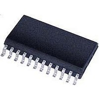
CS5461A-ISZR Cirrus Logic Inc, CS5461A-ISZR Datasheet - Page 18

CS5461A-ISZR
Manufacturer Part Number
CS5461A-ISZR
Description
IC Sngl-Phs Bi-Directional Power/Energy
Manufacturer
Cirrus Logic Inc
Datasheet
1.CS5461A-ISZ.pdf
(44 pages)
Specifications of CS5461A-ISZR
Input Impedance
30 KOhm
Measurement Error
0.1%
Voltage - I/o High
0.8V
Voltage - I/o Low
0.2V
Current - Supply
2.9mA
Voltage - Supply
4.75 V ~ 5.25 V
Operating Temperature
-40°C ~ 85°C
Mounting Type
Surface Mount
Package / Case
24-SSOP
Meter Type
Single Phase
Lead Free Status / RoHS Status
Lead free / RoHS Compliant
For Use With
598-1552 - BOARD EVAL & SOFTWARE CS5461A
Lead Free Status / Rohs Status
Lead free / RoHS Compliant
Available stocks
Company
Part Number
Manufacturer
Quantity
Price
Part Number:
CS5461A-ISZR
Manufacturer:
CIRRUS
Quantity:
20 000
energy level, the energy output pins (E1 and E2) alter-
nate changing states (see Figure 6). The duration
(t
transfer function:
The direction the motor will rotate is determined by the
order of the state changes. When energy is positive, E1
will lead E2. When energy is negative, E2 will lead E1.
The Pulse Width Register (PW) does not affect the step-
per motor format.
5.4.5 Pulse Output
The pulse output E3 is designed to assist with meter cal-
ibration. The pulse-output frequency of E3 is directly
proportional to the active power calculated from the in-
put signals. E3 pulse frequency is derived using a sim-
ular transfer function as E1, but is set by the value in the
PulseRateE
The E3 pin outputs negative and positive energy, but
has no energy direction indicator.
The pulse width of E3 is configurable. The PulseWidth
register defines the pulse width of E3 in units of 1/OWR
or:
The default value is 0.
5.4.6 Anti-creep for the Pulse Outputs
Anti-creep allows the measurement element to maintain
an energy level, such that when the magnitude of the
accumulated active power is below this level, no energy
pulses are output. Anti-creep is enabled by setting bit
FAC in the Control Register for E3 and bit EAC in the
Control Register for E1 and E2.
For low-frequency pulse output formats (i.e. mechanical
counter and stepper motor formats), the active power is
accumulated over time. When a designated energy lev-
el is reached (determined by the transfer function) a
pulse is generated on E1 and/or E2. If active power with
18
edge
E 1
E 2
) between the alternating states is defined by the
. . .
. . .
3
Register.
t pw
t
edge
=
-------------------------------------------- -
(
(
(
sec
MCLK
PulseWidth
E3
)
P o s it iv e E n e r g y
=
)
--------------------- -
FREQ E
⁄
t
K
e d g e
Figure 6. Stepper Motor Format on E1 and E2
)
1
⁄
1024
alternating polarity occurs during the accumulation peri-
od (e.g. random noise at zero power levels), the accura-
cy of the registered energy will be maintained.
For high-frequency pulse output formats (i.e. normal
and alternate pulse formats), the active power is accu-
mulated over time until a ±8x buffer is defined. Then,
when the designated energy level is reached, a pulse is
generated on E1 and/or E2. For pulse outputs with high
frequencies and power levels close to zero, the extend-
ed buffer prevents random noise from being registered
as active energy.
5.4.7 Design Examples
EXAMPLE #1:
The maximum rated levels for a power line meter are
250 V rms and 20 A rms. The required number of puls-
es per second on E1 is 100 pulses per second (100 Hz),
when the levels on the power line are 220 V rms and
15 A rms.
With a 10x gain on the voltage and current channel the
maximum input signal is 250 mV
alog Inputs
channel inputs, the maximum rated rms input levels will
register 0.6 in V
voltage level at the channel inputs will be 150 mV rms
when the maximum rated levels on the power lines are
250 V rms and 20 A rms.
Solving for PulseRateE
Therefore with PF = 1 and
the PulseRateE
VIN
IIN
=
=
220V
15A
PulseRateE
×
×
(
PulseRateE 1 2
(
(
(
150mV
on page 15). To prevent over-driving the
150mV
N e g a t iv e E n e r g y
1,2
RMS
=
)
)
⁄
Register is set to:
---------------------------------------------------------------- -
0.132 10
(
⁄
20A
(
and I
250V
,
)
1,2
×
)
100 2.5
=
)
=
)
RMS
------------------------------------------------------------------ -
VIN VGAIN
using the transfer function:
=
112.5mV
×
×
FREQ E
0.1125
132mV
×
by design. Therefore the
2
P
×
×
10
(see
VREFIN
×
=
IIN
420.8754Hz
CS5461A
Section 5.1 An-
×
2
PF
DS661F2
. . .
. . .


