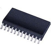
CS5461A-ISZR Cirrus Logic Inc, CS5461A-ISZR Datasheet - Page 13

CS5461A-ISZR
Manufacturer Part Number
CS5461A-ISZR
Description
IC Sngl-Phs Bi-Directional Power/Energy
Manufacturer
Cirrus Logic Inc
Datasheet
1.CS5461A-ISZ.pdf
(44 pages)
Specifications of CS5461A-ISZR
Input Impedance
30 KOhm
Measurement Error
0.1%
Voltage - I/o High
0.8V
Voltage - I/o Low
0.2V
Current - Supply
2.9mA
Voltage - Supply
4.75 V ~ 5.25 V
Operating Temperature
-40°C ~ 85°C
Mounting Type
Surface Mount
Package / Case
24-SSOP
Meter Type
Single Phase
Lead Free Status / RoHS Status
Lead free / RoHS Compliant
For Use With
598-1552 - BOARD EVAL & SOFTWARE CS5461A
Lead Free Status / Rohs Status
Lead free / RoHS Compliant
Available stocks
Company
Part Number
Manufacturer
Quantity
Price
Part Number:
CS5461A-ISZR
Manufacturer:
CIRRUS
Quantity:
20 000
4. THEORY OF OPERATION
The CS5461A is a dual-channel analog-to-digital con-
verter (ADC) followed by a computation engine that per-
forms
conversion. The flow diagram for the two data paths is
depicted in
with two dedicated channels, voltage and current, then
optimized to simplify interfacing to sensing elements.
The voltage-sensing element introduces a voltage
waveform on the voltage channel input VIN± and is sub-
ject to a gain of 10x. A second-order, delta-sigma mod-
ulator samples the amplified signal for digitization.
Simultaneously, the current-sensing element introduces
a voltage waveform on the current channel input IIN±
and is subject to the two selectable gains of the pro-
grammable gain amplifier (PGA). The amplified signal is
sampled by a fourth-order, delta-sigma modulator for
digitization. Both converters sample at a rate of
MCLK/8, the over-sampling provides a wide dynamic
range and simplified anti-alias filter design.
4.1 Digital Filters
The decimating digital filters on both channels are Sinc
filters followed by 4th-order, IIR filters. The single-bit
data is passed to the low-pass decimation filter and out-
put at a fixed word rate. The output word is passed to
the IIR filter to compensate for the magnitude roll-off of
the low-pass filtering operation.
An optional digital High-pass Filter (HPF in
moves any DC component from the selected signal
path. By removing the DC component from the voltage
and/or the current channel, any DC content will also be
removed from the calculated active power as well. With
both HPFs enabled, the DC component will be removed
from the calculated V
ent power.
DS661F2
CURRENT
VOLTAGE
x10
PGA
power
Figure
* DENOTES REGISTER NAME.
2nd Order
Modulator
Modulator
4th Order
calculations
PC6 PC5 PC4 PC3 PC2 PC1 PC0
2. The analog inputs are structured
∆Σ
∆Σ
RMS
Configuration Register *
and I
DELAY
REG
SINC 3
6
RMS
and
SINC 3
DELAY
as well as the appar-
Digital Filter
REG
Digital Filter
energy-to-pulse
SYS
X
X
Gain
Figure
*
Figure 2. Data Flow.
IIR
IIR
2) re-
Option
Option
Option
Option
3
HPF
APF
APF
HPF
When the HPF option is used in only one channel, the
APF (all pass filter) option can be applied to the other
channel to preserve the phase match between the two
channels.
4.2 Voltage and Current Measurements
The digital filter output word is then subject to a DC off-
set adjustment and a gain calibration (See
System Calibration
surement is available to the user by reading the instan-
taneous voltage and current registers.
The Root Mean Square (RMS) calculations are per-
formed on N instantaneous voltage and current sam-
ples, V
using the formula:
and likewise for V
cessible by register reads, which are updated once ev-
ery cycle count (referred to as a computational cycle).
4.3 Power Measurements
The instantaneous voltage and current samples are
multiplied to obtain the instantaneous power (see
ure
sions to compute active power and used to drive energy
pulse outputs E1, E2 and E3. Output E3 provides a uni-
form pulse stream that is proportional to the active pow-
er and is designed for system calibration.
+
+
V
I
DCoff
DCoff
Σ
Σ
+
+
2). The product is then averaged over N conver-
*
*
V
I
n
gn
gn
X
X
and I
*
*
X
+
V *
n
I *
P off *
+
P *
respectively (where N is the cycle count),
Σ
PulseRateE
PulseRateE
RMS
X
X
on page 35). The calibrated mea-
I
RMS
, using V
Σ
Σ
N
N
1,2
3
*
*
=
X
X
÷
÷
------------------- -
n
N 1
∑
n
N
N
=
Σ
–
N
. I
N
Energy-to-pulse
Energy-to-pulse
0
I n
RMS
÷
√
√
and V
N
CS5461A
+
+
V
P
I
Active
ACoff
ACoff
RMS
Σ
Σ
E3
E1
E2
+
Section 7.
+
*
*
*
are ac-
X
Fig-
V
I
RMS
RMS
13
S *
*
*


