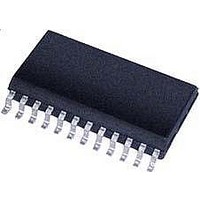
CS5461A-ISZR Cirrus Logic Inc, CS5461A-ISZR Datasheet - Page 17

CS5461A-ISZR
Manufacturer Part Number
CS5461A-ISZR
Description
IC Sngl-Phs Bi-Directional Power/Energy
Manufacturer
Cirrus Logic Inc
Datasheet
1.CS5461A-ISZ.pdf
(44 pages)
Specifications of CS5461A-ISZR
Input Impedance
30 KOhm
Measurement Error
0.1%
Voltage - I/o High
0.8V
Voltage - I/o Low
0.2V
Current - Supply
2.9mA
Voltage - Supply
4.75 V ~ 5.25 V
Operating Temperature
-40°C ~ 85°C
Mounting Type
Surface Mount
Package / Case
24-SSOP
Meter Type
Single Phase
Lead Free Status / RoHS Status
Lead free / RoHS Compliant
For Use With
598-1552 - BOARD EVAL & SOFTWARE CS5461A
Lead Free Status / Rohs Status
Lead free / RoHS Compliant
Available stocks
Company
Part Number
Manufacturer
Quantity
Price
Part Number:
CS5461A-ISZR
Manufacturer:
CIRRUS
Quantity:
20 000
is (MCLK/K)/16. The pulse duration (t
multiple of MCLK cycles, approximately equal to:
The maximum pulse duration (t
sampling rate and the minimum is defined by the maxi-
mum pulse frequency. The t
The Pulse Width Register (PW) does not affect the nor-
mal format.
5.4.2 Alternate Pulse Format
Setting bits MECH = 1 and STEP = 0 in the Control
Register and ALT = 1 in the Configuration Register con-
figures the E1 and E2 pins for alternating pulse format
output (see
tive-low pulses with a pulse duration (t
the Pulse Width Register (PW):
If MCLK = 4.096 MHz, K = 1, and PW = 1 then
t
DS661F2
PW
E2
E1
= 0.25 ms. To ensure that pulses occur on the E1
E2
E1
...
...
-----------------------------------
(MCLK/K)/16
... ...
...
Figure
1
t
dur
t
PW
(
×
4). Each pin produces alternating ac-
sec
8
(
FREQ
ms
<
)
Positive Energy
≅
t
)
dur
------------------------------------------- -
PulseRateE 1 2
=
E
(
sec
---------------------------------------- -
(MCLK/K)/1024
dur
)
Figure 5. Mechanical Counter Format on E1 and E2
<
dur
PW
limits are:
Figure 4. Alternate Pulse Format on E1 and E2
1
---------------------------------------- -
(MCLK/K)/1024
t
PW
) is determined by the
,
×
dur
8
1
PW
) is an integer
) defined by
×
t
PW
8
FREQ
E
and E2 output pins when full-scale input signals are ap-
plied to the voltage and current channels, then:
The pulse frequency (FREQ
PulseRateE
transfer function. The energy direction is not defined in
the alternate pulse format.
5.4.3 Mechanical Counter Format
Setting bits MECH = 1 and STEP = 0 in the Control
Register and bit ALT = 0 in the Configuration Register
enables E1 and E2 for mechanical counters and similar
discrete counting instruments. When energy is nega-
tive, pulses appear on E2 (see Figure 5). When energy
is positive, the pulses appear on E1. The pulse width is
defined by the Pulsewidth Register and will limit the out-
put pulse frequency (FREQ
samples, if MCLK = 4.096 MHz and K = 1 then
t
PulseRateE
value.
5.4.4 Stepper Motor Format
Setting bits STEP = 1 and MECH = 0 in the Control
Register and bit ALT = 0 in the Configuration Register
configures the E1 and E2 pins for stepper motor format.
When the accumulated active power equals the defined
PW
= 128 ms. To ensure that pulses will occur, the
Negative Energy
1,2
1,2
Register and can be calculated using the
Register must be set to an appropriate
PulseRateE 1 2
,
E
E
). By default, PW = 512
) is determined by the
<
----------- -
t
PW
1
CS5461A
...
...
...
...
17


