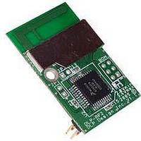
DLP-RF2 DLP Design Inc, DLP-RF2 Datasheet - Page 8

DLP-RF2
Manufacturer Part Number
DLP-RF2
Description
Zigbee / 802.15.4 Modules & Development Tools USE 626-DLP-RF2-Z
Manufacturer
DLP Design Inc
Datasheet
1.DLP-RF2-Z-G.pdf
(12 pages)
Specifications of DLP-RF2
Wireless Frequency
2.4 GHz
Interface Type
2 Wire Serial
Output Power
1 mW
For Use With/related Products
MC13193, MC9S08GT60
Lead Free Status / RoHS Status
Lead free / RoHS Compliant
3.0 Low-Power Mode (RF2-Z Only)
At power up, if MC9S08GT60 Port Pin PTC1 (Header Pin 16) is held low, the module will check
the initial state of selected port pins and immediately enter Low-Power Mode. This mode is a
feature of the SIPP firmware and is only available if using the DLP-RF2-Z with its firmware as
shipped from DLP Design. Total current draw for the DLP-RF2-Z module in this state is
specified at less than 40 microamps at 3V. If pull-ups are enabled and a corresponding port pin
is held low, then shutdown current will be higher. Also, if the user electronics draw any current
from port pins in Sleep Mode, then the shutdown current will be higher. In this state, the
MC13193 transceiver IC is in Hibernate Mode, and the MC9S08GT60 is in Stop Mode.
The data byte stored at EEPROM Location 8 contains a bit field that is used to select which port
pins are to be watched for any change while in Low-Power or Idle Mode. For example, if a “1” is
set for Bit 7 at EEPROM Location 8, and if Port Pin PTA6 is set up as a digital input, and the
state of PTA6 changes (low to high, or high to low), then the MC9S08GT60 is brought out of
Low-Power Mode, and a packet is sent as a broadcast packet (Source ID=0) containing
Command 0xC1.
Bit Position:
Port Pin (RF2):
Port Pin (RF2-Z):
The data bytes stored at EEPROM Locations 4 and 5 hold values that, when combined, are
used to set the length of time that the DLP-RF2-Z will remain asleep or in Low-Power Mode.
The range of time that the DLP-RF2-Z can be left asleep is from 5 seconds to 3.8 days. When
this amount of time has elapsed, the MC9S08GT60 is brought out of Low-Power Mode, and a
packet is sent as a broadcast packet (Destination ID=0) containing Command 0xC2.
The DLP-RF2-Z transmits a broadcast packet (Destination ID=0) for either wake from sleep or
change of a selected digital input. It is the user’s responsibility to establish a DLP-RF1 or
DLP-RF2-Z transceiver as a system controller to receive and process this packet. (Note that
multiple transceivers can be set up as system controllers as long as only one responds to a
wake-from-sleep packet from a specific DLP-RF2-Z.) If the DLP-RF2-Z does not receive a reply
to this packet after a preset length of time, it will return to Sleep Mode to conserve battery
power. Command 0xA4 can be sent to the DLP-RF2-Z to instruct it to return to Sleep Mode
immediately, or the system controller can first request data from the DLP-RF2-Z before
instructing it to return to sleep.
The data byte stored at EEPROM Location 6 contains a value that determines how many half-
seconds a DLP-RF2-Z will remain awake waiting for a response from the system controller. If
this value is set to 2 (for example), then the DLP-RF2-Z will transmit its wake-from-sleep packet,
wait for 500 milliseconds for a reply, and retry one additional time before giving up and returning
to sleep.
Rev 1.8 (November 2005)
D7
A6
A6
D6
B6
B6
D5
B5
A2
D4
B4
A1
8
D3
B3
B3
D2
B2
B2
B1
B1
DLP-RF2-Z DLP Design, Inc.
D1
D0
B0
B0
EEPROM [8]


