DLP-RF2 DLP Design Inc, DLP-RF2 Datasheet - Page 3
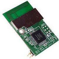
DLP-RF2
Manufacturer Part Number
DLP-RF2
Description
Zigbee / 802.15.4 Modules & Development Tools USE 626-DLP-RF2-Z
Manufacturer
DLP Design Inc
Datasheet
1.DLP-RF2-Z-G.pdf
(12 pages)
Specifications of DLP-RF2
Wireless Frequency
2.4 GHz
Interface Type
2 Wire Serial
Output Power
1 mW
For Use With/related Products
MC13193, MC9S08GT60
Lead Free Status / RoHS Status
Lead free / RoHS Compliant


(purchased separately).] Connection to the RF2-Z for the purpose of setup and test can also be
made via RF from another RF1 or RF2-Z.
**Under this communication protocol, it is the responsibility of the serial host application
firmware to “Retry” transmissions that do not produce the anticipated reply.**
2.1 Packet Structure
Each SIPP firmware packet is comprised of 6 or more bytes. The following table outlines the
packet structure:
PACKET STRUCTURE
*Note: Each transceiver in the system must have a unique ID. ID:0 is reserved for broadcast packets
2.2 Reserved EEPROM Locations
The EEPROM memory is a feature of the SIPP firmware and, as such, is only available if using
the DLP-RF2-Z with its firmware as shipped from DLP Design.
The EEPROM memory used by the SIPP firmware consists of a block of 32 bytes that reside
within the Flash program memory of the MC9S08GT60. The first 10 bytes (0-9) and the last
byte (31) are reserved for storing transceiver settings and checksum. Bytes 10 through 30
(user area) are available for use by user’s host software.
Whenever the data in any EEPROM location is changed, the checksum location (EEPROM
Location 31) is automatically updated. At power up (or reset), if ever the calculated checksum
for the first 31 bytes does not match the value at EEPROM Location 31, the Default Reset
values for the transceiver settings are restored, and the checksum is recalculated and rewritten.
The values in the user area are preserved.
Rev 1.8 (November 2005)
Byte Description
0
1
2
3
4
5
6
sent by DLP-RF2-Z transceivers coming out of Sleep Mode.
Number of bytes in the packet
following byte 0: 5-124
Destination ID MSByte
ID Range: 1-65535*
Destination ID LSByte
Source ID MSByte
Range: 1-65535
Source ID LSByte
Command Byte
Command Range: 0xA0-0xDF
Data Byte(s)
Comments
Each packet must contain (as a minimum) the
number of bytes, a destination ID, Source ID
and a command byte
ID:1 default for new DLP-RF1 transceivers
ID:2 default for new DLP-RF2-Z transceivers
ID:0 reserved for broadcast to all transceivers
Both Command Packets and Reply Packets.
Every packet must have a command byte.
0-119 bytes of data are allowed in the packet
3
DLP-RF2-Z DLP Design, Inc.
Related parts for DLP-RF2
Image
Part Number
Description
Manufacturer
Datasheet
Request
R

Part Number:
Description:
MODULE USB-TO-TTL PARL FIFO CONV
Manufacturer:
DLP Design Inc
Datasheet:

Part Number:
Description:
MODULE DATA-ACQUISITION 8-CH
Manufacturer:
DLP Design Inc
Datasheet:

Part Number:
Description:
MODULE DATA-ACQUISITION 20-CH
Manufacturer:
DLP Design Inc
Datasheet:

Part Number:
Description:
RFID READER/WRITER SNGL-CH OEM
Manufacturer:
DLP Design Inc
Datasheet:

Part Number:
Description:
Interface Modules & Development Tools DLP-245PL PACKAGED w/CCS Compiler
Manufacturer:
DLP Design Inc

Part Number:
Description:
Interface Modules & Development Tools DLP-245PB-G BOARD + CCS Compiler
Manufacturer:
DLP Design Inc
Datasheet:

Part Number:
Description:
Interface Modules & Development Tools DLP-TILT SENSOR ACCEL VIBRATION
Manufacturer:
DLP Design Inc

Part Number:
Description:
MODULE USB-TO-PARL FIFO 18-DIP
Manufacturer:
DLP Design Inc
Datasheet:

Part Number:
Description:
MODULE USB-MCU FT245RL W/16F877A
Manufacturer:
DLP Design Inc
Datasheet:

Part Number:
Description:
MODULE USB-TO-FPGA TRAINING TOOL
Manufacturer:
DLP Design Inc
Datasheet:

Part Number:
Description:
MODULE USB-MCU FT232R W/18F2410
Manufacturer:
DLP Design Inc
Datasheet:

Part Number:
Description:
MODULE USB-MCU FT245RL W/SX48
Manufacturer:
DLP Design Inc
Datasheet:

Part Number:
Description:
MODULE USB-MCU FT2232D W/16F877A
Manufacturer:
DLP Design Inc
Datasheet:

Part Number:
Description:
MODULE USB-TO-FPGA SPARTAN3
Manufacturer:
DLP Design Inc
Datasheet:

Part Number:
Description:
MOD USB-MCU FT245RL W/18LF8722
Manufacturer:
DLP Design Inc
Datasheet: