DLP-RF2 DLP Design Inc, DLP-RF2 Datasheet - Page 2
DLP-RF2
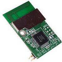
Manufacturer Part Number
DLP-RF2
Description
Zigbee / 802.15.4 Modules & Development Tools USE 626-DLP-RF2-Z
Manufacturer
DLP Design Inc
Datasheet
1.DLP-RF2-Z-G.pdf
(12 pages)
Specifications of DLP-RF2
Wireless Frequency
2.4 GHz
Interface Type
2 Wire Serial
Output Power
1 mW
For Use With/related Products
MC13193, MC9S08GT60
Lead Free Status / RoHS Status
Lead free / RoHS Compliant


1.0 System Overview
Using the pre-programmed SIPP firmware, the DLP-RF2-Z can be used in conjunction with
other DLP-RF2-Z and/or DLP-RF1 modules to form simple point-to-point and star configuration
systems. Both the DLP-RF1 and the DLP-RF2-Z can serve as host/system controllers. In the
case of the DLP-RF1, the host is a user-supplied Windows, Linux, or Mac PC that is accessed
via a USB interface and user-supplied, 6-foot USB cable. In the case of the DLP-RF2-Z, the
host is a user-supplied microcontroller/DSP/FPGA/etc. that is accessed via a 2-wire serial
interface–TX, RX, and ground. A host processor is not necessarily required by the DLP-RF2-Z.
The SIPP firmware within the DLP-RF2-Z can be accessed remotely via another transceiver and
can be used to both gain access to the MC9S08GT60’s port pins for basic digital I/O and offer a
few hardware-specific functions for measuring system power supply voltage, measuring
temperature, and controlling relays. These functions require the presence of external hardware
(purchased separately).
Using the ZigBee Protocol (licensed separately), the DLP-RF2-Z can be used in conjunction
with other DLP-RF1/DLP-RF2-Z transceivers as well as other MC13193-based ZigBee-ready
devices to form complex point-to-point, star, and mesh networks.
In a system using the preprogrammed SIPP firmware, each transceiver has a unique 16-bit ID
yielding a theoretical maximum of 65,535 transceivers. Every data packet handled by the SIPP
firmware must contain, at minimum, the number of bytes in the packet, the destination
transceiver ID (packet destination), the source transceiver ID (packet origin), and a command
byte.
As shipped from DLP Design, the DLP-RF2-Z has an ID of 2. If more than one DLP-RF2-Z is to
be used in a system, then this ID must be changed to a value higher than 2. Upon reset or
power up, the ID is read from non-volatile EEPROM memory. If JP1 is shorted at power up (or
before a reset), the default ID for the DLP-RF2-Z is set to 2 and other transceiver settings are
also returned to a default state in the EEPROM. (Refer to Section 2.2 for additional details.)
In addition to basic packet processing and port-pin manipulation, the SIPP firmware in the
DLP-RF2-Z offers a Low-Power Mode designed to conserve battery power. Holding PTC1
(Header Pin 16) low at power up enables the Low-Power Mode. Once enabled, the DLP-RF2-Z
is in Sleep Mode until awakened by activity on digital inputs that have been enabled to wake the
processor—or by a simple preset timeout. The setup parameters for this feature are also stored
in the non-volatile EEPROM memory. If PTC1 is not held low, then the microcontroller and
RF IC remain in full power mode, offering the fastest packet processing possible. (Refer to
Section 2.2 for additional details.)
2.0 Preprogrammed Serial Interface Packet Processor (SIPP) Firmware
The source code for Freescale’s SMAC is available as a free download from
www.freescale.com. The SIPP firmware is based on the SMAC firmware.
A test program (DLP-RFTestAp.exe) is available as a free download from
www.dlpdesign.com
that makes easy work of setting up the DLP-RF2-Z transceiver and testing its basic functionality.
Use of the DLP-RFTestAp.exe requires a serial interface between a host Windows PC and the
DLP-RF2-Z. [For example, the USB interface available on the upcoming DLP-RF2-ZPROTO
DLP-RF2-Z DLP Design, Inc.
2
Rev 1.8 (November 2005)
Related parts for DLP-RF2
Image
Part Number
Description
Manufacturer
Datasheet
Request
R

Part Number:
Description:
MODULE USB-TO-TTL PARL FIFO CONV
Manufacturer:
DLP Design Inc
Datasheet:

Part Number:
Description:
MODULE DATA-ACQUISITION 8-CH
Manufacturer:
DLP Design Inc
Datasheet:

Part Number:
Description:
MODULE DATA-ACQUISITION 20-CH
Manufacturer:
DLP Design Inc
Datasheet:

Part Number:
Description:
RFID READER/WRITER SNGL-CH OEM
Manufacturer:
DLP Design Inc
Datasheet:

Part Number:
Description:
Interface Modules & Development Tools DLP-245PL PACKAGED w/CCS Compiler
Manufacturer:
DLP Design Inc

Part Number:
Description:
Interface Modules & Development Tools DLP-245PB-G BOARD + CCS Compiler
Manufacturer:
DLP Design Inc
Datasheet:

Part Number:
Description:
Interface Modules & Development Tools DLP-TILT SENSOR ACCEL VIBRATION
Manufacturer:
DLP Design Inc

Part Number:
Description:
MODULE USB-TO-PARL FIFO 18-DIP
Manufacturer:
DLP Design Inc
Datasheet:

Part Number:
Description:
MODULE USB-MCU FT245RL W/16F877A
Manufacturer:
DLP Design Inc
Datasheet:

Part Number:
Description:
MODULE USB-TO-FPGA TRAINING TOOL
Manufacturer:
DLP Design Inc
Datasheet:

Part Number:
Description:
MODULE USB-MCU FT232R W/18F2410
Manufacturer:
DLP Design Inc
Datasheet:

Part Number:
Description:
MODULE USB-MCU FT245RL W/SX48
Manufacturer:
DLP Design Inc
Datasheet:

Part Number:
Description:
MODULE USB-MCU FT2232D W/16F877A
Manufacturer:
DLP Design Inc
Datasheet:

Part Number:
Description:
MODULE USB-TO-FPGA SPARTAN3
Manufacturer:
DLP Design Inc
Datasheet:

Part Number:
Description:
MOD USB-MCU FT245RL W/18LF8722
Manufacturer:
DLP Design Inc
Datasheet: