A16-1NRN Omron, A16-1NRN Datasheet - Page 247
A16-1NRN
Manufacturer Part Number
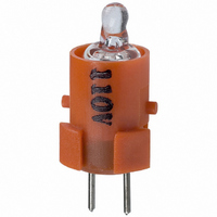
A16-1NRN
Description
NEON LAMP 110V RED FOR A16
Manufacturer
Omron
Type
Neon Lamp, 110 VoltsACr
Series
A16r
Datasheets
1.M2DA-7001.pdf
(265 pages)
2.A16-1NRN.pdf
(30 pages)
3.A16-2.pdf
(27 pages)
4.A165-CAA.pdf
(17 pages)
Specifications of A16-1NRN
Accessory Type
Neon Lamp Replacement
Supply Voltage
110V
Base Type
Bi-Pin
Colour
Red
Current Rating
1.5mA
Svhc
No SVHC (15-Dec-2010)
Illumination Colour
Red
Operating Lifetime
10000h
Voltage Rating Vac
110V
Average Bulb Life
1000
Color
Red
Illumination
Illuminated
Height
13 mm
Illumination Color
Red
Mounting Style
Snap In
Termination Style
Tabs
Lamp Base Type
Bi-Pin
Rohs Compliant
Yes
Lead Free Status / RoHS Status
Lead free / RoHS Compliant
For Use With/related Products
A16 Series
For Use With
Z1397 - SWTCH KNOB RND 3POS DPDT ILL REDZ1394 - SWTCH KNOB RND 2POS SPDT ILL REDZ1391 - SWTCH KNOB RND 2POS SPDT ILL REDZ1385 - SWITCH KNB RECT 3POS DPDT ILLZ1382 - SWITCH KNB RECT 2POS SPDT ILLZ1379 - SWITCH KNB RECT 2POS SPDT ILLZ1373 - SWITCH KNOB SQ 3-POS DPDT ILLZ1370 - SWITCH KNOB SQ 2-POS SPDT ILLZ1367 - SWITCH KNOB SQ 2-POS SPDT ILLZ1309 - SWITCH PB RND MOM DPDT ILLUM REDZ1305 - SWITCH PB RECT MOM DPDT ILLUMZ1301 - SWITCH PB SQ MOM DPDT ILLUM RED
Lead Free Status / Rohs Status
Lead free / RoHS Compliant
Other names
A161NRN
Z1342
Z1342


A3P
Precautions
Refer to the Common Precautions for Pushbutton Switches on
page 14.
Correct Use
Mounting
Always make sure that the power is turned OFF before mounting,
removing, or wiring the Switch, or performing maintenance.
After wiring the Switch, make sure that there is a suitable isolation
distance.
Wiring
Perform soldering promptly and correctly at 60 W maximum and
within 3 seconds. (Dip soldering temperature 280_C max.) Wait for
one minute after soldering before exerting any external force on the
solder.
Operating Environment
Do not use in locations that are subject to dust, oil, or metal filings as
these may penetrate the interior of the Switch and cause malfunc-
tion.
LED (for VDC)
Check the terminal polarity when wiring.
The rated voltage is shown on the plate on the back of the lighting
unit, so be sure to use within the voltage shown.
An LED current-limiting resistor is built in, so there is no need to
mount an external resistor.
Incandescent Lamp
Apply 80% of the rated voltage (operating voltage) to the incandes-
cent lamp to improve life expectancy and incandescence.
Character Plate (Character Film)
If preparing the character plate separately, use a heat-resistant film
with a thickness of 0.1 to 0.3 mm.
Do not apply a voltage higher than the maximum rated operat-
ing voltage between the lamp terminals, as there is a risk that
the incandescent lamp or LED will be damaged, and the Push-
button will be ejected.
When replacing the incandescent lamp, first turn OFF the
power supply, and then wait 10 minutes before performing re-
placement, as the lamp is still hot immediately after the power
is turned OFF, so there is a risk of burns.
!
Caution
24.8
–0.3
+0.
dia.
23±0.1 dia.
Using Microloads
Using a standard load switch when a microload circuit is opened or
closed may cause wear on the contacts. Use the switch within the
operating range. (Refer to the diagram below.) Even when using mi-
croload models within the operating range shown below, if inrush
current occurs when the contact is opened or closed, it may cause
the contact surface to become rough, and so decrease life expec-
tancy. Therefore, insert a contact protection circuit where neces-
sary. The minimum applicable load is the N-level reference value.
This value indicates the malfunction reference level for the reliability
level of 60% (λ 60) (conforming to JIS C5003). The equation, λ 60 =
0.5 x 10
than 1/2,000,000 with a reliability level of 60%.
Others
If the panel is to be finished (e.g., coated), make sure that the panel
meets the specified dimensions after the coating.
–4
/time indicates that the estimated malfunction rate is less
Invalid
area
Microload
area
Current (mA)
Standard
load area
A3P
245
Related parts for A16-1NRN
Image
Part Number
Description
Manufacturer
Datasheet
Request
R

Part Number:
Description:
SWITCH PB SQUARE MOM SPDT GREEN
Manufacturer:
Omron
Datasheet:

Part Number:
Description:
SWITCH PB SQUARE MOM SPDT WHITE
Manufacturer:
Omron
Datasheet:
Part Number:
Description:
SWITCH PB SQUARE MOM SPDT YELLOW
Manufacturer:
Omron
Datasheet:
Part Number:
Description:
SWITCH PB RECTANG MOM SPDT BLUE
Manufacturer:
Omron
Datasheet:
Part Number:
Description:
SWITCH PB RECTANG MOM SPDT YEL
Manufacturer:
Omron
Datasheet:
Part Number:
Description:
SWITCH PB SQUARE MOM SPDT BLUE
Manufacturer:
Omron
Datasheet:
Part Number:
Description:
SWITCH PB SQUARE MOM SPDT RED
Manufacturer:
Omron
Datasheet:
Part Number:
Description:
SWITCH PB RECTANG MOM SPDT GREEN
Manufacturer:
Omron
Datasheet:
Part Number:
Description:
SWITCH PB RECTANG MOM SPDT RED
Manufacturer:
Omron
Datasheet:

Part Number:
Description:
SWITCH PB RECTANG MOM SPDT WHITE
Manufacturer:
Omron
Datasheet:
Part Number:
Description:
SWITCH PB ROUND MOM SPDT BLUE
Manufacturer:
Omron
Datasheet:
Part Number:
Description:
SWITCH PB ROUND MOM SPDT GREEN
Manufacturer:
Omron
Datasheet:
Part Number:
Description:
SWITCH PB ROUND MOM SPDT RED
Manufacturer:
Omron
Datasheet:
Part Number:
Description:
SWITCH PB ROUND MOM SPDT WHITE
Manufacturer:
Omron
Datasheet:
Part Number:
Description:
SWITCH PB ROUND MOM SPDT YELLOW
Manufacturer:
Omron
Datasheet: