A16-1NRN Omron, A16-1NRN Datasheet - Page 161
A16-1NRN
Manufacturer Part Number
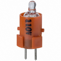
A16-1NRN
Description
NEON LAMP 110V RED FOR A16
Manufacturer
Omron
Type
Neon Lamp, 110 VoltsACr
Series
A16r
Datasheets
1.M2DA-7001.pdf
(265 pages)
2.A16-1NRN.pdf
(30 pages)
3.A16-2.pdf
(27 pages)
4.A165-CAA.pdf
(17 pages)
Specifications of A16-1NRN
Accessory Type
Neon Lamp Replacement
Supply Voltage
110V
Base Type
Bi-Pin
Colour
Red
Current Rating
1.5mA
Svhc
No SVHC (15-Dec-2010)
Illumination Colour
Red
Operating Lifetime
10000h
Voltage Rating Vac
110V
Average Bulb Life
1000
Color
Red
Illumination
Illuminated
Height
13 mm
Illumination Color
Red
Mounting Style
Snap In
Termination Style
Tabs
Lamp Base Type
Bi-Pin
Rohs Compliant
Yes
Lead Free Status / RoHS Status
Lead free / RoHS Compliant
For Use With/related Products
A16 Series
For Use With
Z1397 - SWTCH KNOB RND 3POS DPDT ILL REDZ1394 - SWTCH KNOB RND 2POS SPDT ILL REDZ1391 - SWTCH KNOB RND 2POS SPDT ILL REDZ1385 - SWITCH KNB RECT 3POS DPDT ILLZ1382 - SWITCH KNB RECT 2POS SPDT ILLZ1379 - SWITCH KNB RECT 2POS SPDT ILLZ1373 - SWITCH KNOB SQ 3-POS DPDT ILLZ1370 - SWITCH KNOB SQ 2-POS SPDT ILLZ1367 - SWITCH KNOB SQ 2-POS SPDT ILLZ1309 - SWITCH PB RND MOM DPDT ILLUM REDZ1305 - SWITCH PB RECT MOM DPDT ILLUMZ1301 - SWITCH PB SQ MOM DPDT ILLUM RED
Lead Free Status / Rohs Status
Lead free / RoHS Compliant
Other names
A161NRN
Z1342
Z1342


Installation
Common to A22, A22S/W, A22K, M22, and A22E
Panel Hole Dimensions
For 25-dia. holes, always use 25-dia. Rings. (Since the cutout dimen-
sions are large, IP65 cannot be guaranteed unless 25-dia. Rings are
used.)
If outer surface treatment such as coating is performed for the panel,
the panel dimensions after outer surface treatment must meet the
specified panel dimensions.
Note: Recommended panel thickness: 1 to 5 mm.
Matrix Installation
1. The following panel hole dimensions apply when Switch Unit and
the Standard-size Legend Plate Frame and Lock Ring are
mounted, and lead wires are connected directly to the Switch
Block.
Mounting to the Panel
22 dia.
A
25 dia.
2. The following panel hole dimensions apply when the Large-size
Pitches A and B between the centers of the mounting holes are as
follows:
For 1. above:
For 2. above:
Note: 1. The above dimensions are the minimum dimensions for
A22-10, A22-10S, A22-01, A22-01S
A22-20, A22-20S, A22-02, A22-02S, A22-11,
A22-11S
Bare crimp termi-
nals
Crimp terminals
with insulating
sheath
Legend Plate Frame is mounted, and when crimp terminals are
connected to the Switch Block terminals.
Type of crimp
terminal
2. With pushbuttons of external dimensions greater than
3. When using a pushbutton with external dimensions exceed-
when the wires described under Applicable Wire Size on
page 165 are used. If a different wires are used, the wiring
dimensions may be different so determine an appropriate
pitch before setup.
30 mm, set the pitch according to the dimensions. (When
using matrix installation for the A22-M@, mount with a pitch
of 40 mm instead of 30 mm in the diagram above.)
ing 30 mm, use a pitch appropriate for the pushbutton.
Switch Blocks
A22-10, A22-10S, A22-01,
A22-01S
A22-20, A22-20S, A22-02,
A22-02S, A22-11, A22-11S
A22-10, A22-10S, A22-01,
A22-01S
A22-20, A22-20S, A22-02,
A22-02S, A22-11, A22-11S
Switch Blocks
B
45 mm min.
55 mm min.
51 mm min.
61 mm min.
60 mm min.
70 mm min.
A
B
159
Related parts for A16-1NRN
Image
Part Number
Description
Manufacturer
Datasheet
Request
R

Part Number:
Description:
SWITCH PB SQUARE MOM SPDT GREEN
Manufacturer:
Omron
Datasheet:

Part Number:
Description:
SWITCH PB SQUARE MOM SPDT WHITE
Manufacturer:
Omron
Datasheet:
Part Number:
Description:
SWITCH PB SQUARE MOM SPDT YELLOW
Manufacturer:
Omron
Datasheet:
Part Number:
Description:
SWITCH PB RECTANG MOM SPDT BLUE
Manufacturer:
Omron
Datasheet:
Part Number:
Description:
SWITCH PB RECTANG MOM SPDT YEL
Manufacturer:
Omron
Datasheet:
Part Number:
Description:
SWITCH PB SQUARE MOM SPDT BLUE
Manufacturer:
Omron
Datasheet:
Part Number:
Description:
SWITCH PB SQUARE MOM SPDT RED
Manufacturer:
Omron
Datasheet:
Part Number:
Description:
SWITCH PB RECTANG MOM SPDT GREEN
Manufacturer:
Omron
Datasheet:
Part Number:
Description:
SWITCH PB RECTANG MOM SPDT RED
Manufacturer:
Omron
Datasheet:

Part Number:
Description:
SWITCH PB RECTANG MOM SPDT WHITE
Manufacturer:
Omron
Datasheet:
Part Number:
Description:
SWITCH PB ROUND MOM SPDT BLUE
Manufacturer:
Omron
Datasheet:
Part Number:
Description:
SWITCH PB ROUND MOM SPDT GREEN
Manufacturer:
Omron
Datasheet:
Part Number:
Description:
SWITCH PB ROUND MOM SPDT RED
Manufacturer:
Omron
Datasheet:
Part Number:
Description:
SWITCH PB ROUND MOM SPDT WHITE
Manufacturer:
Omron
Datasheet:
Part Number:
Description:
SWITCH PB ROUND MOM SPDT YELLOW
Manufacturer:
Omron
Datasheet: