A16-1NRN Omron, A16-1NRN Datasheet - Page 203
A16-1NRN
Manufacturer Part Number
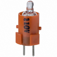
A16-1NRN
Description
NEON LAMP 110V RED FOR A16
Manufacturer
Omron
Type
Neon Lamp, 110 VoltsACr
Series
A16r
Datasheets
1.M2DA-7001.pdf
(265 pages)
2.A16-1NRN.pdf
(30 pages)
3.A16-2.pdf
(27 pages)
4.A165-CAA.pdf
(17 pages)
Specifications of A16-1NRN
Accessory Type
Neon Lamp Replacement
Supply Voltage
110V
Base Type
Bi-Pin
Colour
Red
Current Rating
1.5mA
Svhc
No SVHC (15-Dec-2010)
Illumination Colour
Red
Operating Lifetime
10000h
Voltage Rating Vac
110V
Average Bulb Life
1000
Color
Red
Illumination
Illuminated
Height
13 mm
Illumination Color
Red
Mounting Style
Snap In
Termination Style
Tabs
Lamp Base Type
Bi-Pin
Rohs Compliant
Yes
Lead Free Status / RoHS Status
Lead free / RoHS Compliant
For Use With/related Products
A16 Series
For Use With
Z1397 - SWTCH KNOB RND 3POS DPDT ILL REDZ1394 - SWTCH KNOB RND 2POS SPDT ILL REDZ1391 - SWTCH KNOB RND 2POS SPDT ILL REDZ1385 - SWITCH KNB RECT 3POS DPDT ILLZ1382 - SWITCH KNB RECT 2POS SPDT ILLZ1379 - SWITCH KNB RECT 2POS SPDT ILLZ1373 - SWITCH KNOB SQ 3-POS DPDT ILLZ1370 - SWITCH KNOB SQ 2-POS SPDT ILLZ1367 - SWITCH KNOB SQ 2-POS SPDT ILLZ1309 - SWITCH PB RND MOM DPDT ILLUM REDZ1305 - SWITCH PB RECT MOM DPDT ILLUMZ1301 - SWITCH PB SQ MOM DPDT ILLUM RED
Lead Free Status / Rohs Status
Lead free / RoHS Compliant
Other names
A161NRN
Z1342
Z1342


Safety Precautions
Refer to the Common Precautions for Pushbutton Switches on page 14.
Mounting
Always make sure that the power is turned OFF before mounting,
removing, or wiring the Switch, or performing maintenance. Electric
shock may occur.
Do not tighten the mounting ring more than necessary using tools
such as pointed-nose pliers. Doing so will damage the mounting ring.
The tightening torque is 0.98 to 1.96 N·m.
Recommended panel thickness: 1 to 5 mm.
Wiring
When DC-specific LEDs are used, wire the Switch so that the X1 ter-
minal is positive.
Terminal screws must be Phillips or slotted M3.5 screws with a
square washer.
The tightening torque is 1.08 to 1.27 N·m.
Single wires, stranded wires, and crimp terminals can be connected
to the Switch.
Applicable Wiring Materials:
Twisted strands: 2 mm
Solid wire: 1.6 mm dia.
Naked Crimp Terminals
After wiring the Switch, maintain an appropriate clearance and
creepage distance.
Operating Environment
The IP65 model is designed with a protective structure so that it will
not sustain damage if it is subjected to water from any direction to the
front of the panel.
Using the Microload
Contact failure may occur is a Switch designed for a standard load is
used to switch a microload. Use Switches within the application
ranges shown in the following graph. Even within the application
range, insert a contact protection circuit, if necessary, to prevent the
reduction of life expectancy due to extreme wear on the contacts
caused by loads where inrush current occurs when the contact is
opened and closed.
The minimum applicable load is the N-level reference value. This
value indicates the malfunction reference level for the reliability level
of 60% ( 60) (conforming to JIS C5003).
The equation,
function rate is less than 1/2,000,000 with a reliability level of 60%.
Crimp Terminals with
Insulating Sheaths
Cat. No. A119-E1-06
Do not apply a voltage exceeding the rated voltage across the incan-
descent lamp terminals.
The lamp may be destroyed and the operation unit may fly out.
Precautions for Correct Use
!Caution
60 = 0.5 x 10
ALL DIMENSIONS SHOWN ARE IN MILLIMETERS.
To convert millimeters into inches, multiply by 0.03937. To convert grams into ounces, multiply by 0.03527.
2
max.
6
20.2 mm max.
16.0 mm max.
/time indicates that the estimated mal-
In the interest of product improvement, specifications are subject to change without notice.
8 mm max.
8 mm max.
20.2 mm max.
16.0 mm max.
8 mm dia. max.
8 mm dia. max.
LEDs
The LED current-limiting resistor is built-in, so internal resistance is
not required.
If commercially available LEDs are used, select the ones that meet
the following conditions:
Base: BA9S/13@
Overall length: 26 mm max.
Power consumption: 2.6 W max.
Others
The oil-resistant IP65 uses NBR rubber and is resistant to general
cutting oil and cooling oil. Some particular oils cannot be used with
the oil-resistant IP65, however, so contact your OMRON representa-
tive for details.
If the panel is to be finished with coating, etc., make sure that the
panel meets the specified dimensions after the coating.
Do not subject the Switch to extreme shock or vibration. Doing so will
cause malfunctions and damage to the Switch.
Do not let sharp objects come into contact with the Switches that are
made of resin. Doing so will damage the Switches, causing
scratches on the outside of the Pushbuttons, and malfunction.
When handling the Switches, do not throw or drop them.
Hammer
30
12
24
5
0
0.1
0.16 mA
Invalid
area
1 mA
Screwdriver
1
1.6 mA
Microload area
10 mA
10
Do not allow the
Switch to drop and hit
the ground.
Do not place or drop
heavy objects on the
Switch.
Do not operate the
Switch with hard or
sharp objects.
Current (mA)
100 mA
100
Standard
load area
Area of
use
1,000
201
Related parts for A16-1NRN
Image
Part Number
Description
Manufacturer
Datasheet
Request
R

Part Number:
Description:
SWITCH PB SQUARE MOM SPDT GREEN
Manufacturer:
Omron
Datasheet:

Part Number:
Description:
SWITCH PB SQUARE MOM SPDT WHITE
Manufacturer:
Omron
Datasheet:
Part Number:
Description:
SWITCH PB SQUARE MOM SPDT YELLOW
Manufacturer:
Omron
Datasheet:
Part Number:
Description:
SWITCH PB RECTANG MOM SPDT BLUE
Manufacturer:
Omron
Datasheet:
Part Number:
Description:
SWITCH PB RECTANG MOM SPDT YEL
Manufacturer:
Omron
Datasheet:
Part Number:
Description:
SWITCH PB SQUARE MOM SPDT BLUE
Manufacturer:
Omron
Datasheet:
Part Number:
Description:
SWITCH PB SQUARE MOM SPDT RED
Manufacturer:
Omron
Datasheet:
Part Number:
Description:
SWITCH PB RECTANG MOM SPDT GREEN
Manufacturer:
Omron
Datasheet:
Part Number:
Description:
SWITCH PB RECTANG MOM SPDT RED
Manufacturer:
Omron
Datasheet:

Part Number:
Description:
SWITCH PB RECTANG MOM SPDT WHITE
Manufacturer:
Omron
Datasheet:
Part Number:
Description:
SWITCH PB ROUND MOM SPDT BLUE
Manufacturer:
Omron
Datasheet:
Part Number:
Description:
SWITCH PB ROUND MOM SPDT GREEN
Manufacturer:
Omron
Datasheet:
Part Number:
Description:
SWITCH PB ROUND MOM SPDT RED
Manufacturer:
Omron
Datasheet:
Part Number:
Description:
SWITCH PB ROUND MOM SPDT WHITE
Manufacturer:
Omron
Datasheet:
Part Number:
Description:
SWITCH PB ROUND MOM SPDT YELLOW
Manufacturer:
Omron
Datasheet: