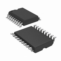
RFHCS362GT-I/SO Microchip Technology, RFHCS362GT-I/SO Datasheet - Page 22

RFHCS362GT-I/SO
Manufacturer Part Number
RFHCS362GT-I/SO
Description
IC CODE HOPPNG ENCDR W/RF 18SOIC
Manufacturer
Microchip Technology
Datasheet
1.RFHCS362F-ISS.pdf
(60 pages)
Specifications of RFHCS362GT-I/SO
Frequency
310MHz ~ 440MHz
Applications
Automotive, Building Access, Garage Openers
Modulation Or Protocol
ASK, FSK
Data Rate - Maximum
3.3 kbps
Power - Output
-12dBm ~ 2dBm
Current - Transmitting
11.5mA
Data Interface
PCB, Surface Mount
Antenna Connector
PCB, Surface Mount
Voltage - Supply
2.2 V ~ 5.5 V
Operating Temperature
-40°C ~ 85°C
Package / Case
18-SOIC (0.300", 7.50mm Width)
Lead Free Status / RoHS Status
Lead free / RoHS Compliant
Features
-
Memory Size
-
rfHCS362G/362F
TABLE 4-2:
4.5
There are 36 configuration bits stored in the EEPROM
array. They are used by the device to determine trans-
mission speed, format, delays and Guard times. They
are
CONFIG_0
SEED_3
this section.
4.5.1
The internal oscillator can be tuned to ±10%. (
selects the nominal value,
0111
the programmer’s responsibility to determine the opti-
mal calibration value.
4.5.2
The low voltage threshold can be programmed to be
any of the values shown in Table 4-2.
DS41189A-page 22
Address
grouped
the slowest). When programming the device, it is
Bit
word. A description of each of the bits follows
10
11
12
13
14
15
0
1
2
3
4
5
6
7
8
9
Configuration Words
OSC
VLOW[0..2]
,
CONFIG_1
in
CONFIG_0
TIMOUT_0
TIMOUT_1
GUARD_0
GUARD_1
three
VLOW_0
VLOW_1
VLOW_2
BSEL_0
BSEL_1
OSC_0
OSC_1
OSC_2
OSC_3
MTX_0
MTX_1
CTSEL
Field
and the upper nybble of the
1000
Configuration
the fastest value and
Minimum number of code
Guard time select
Oscillator adjust
Time-out select
Bit rate select
Description
V
LOW
Words:
CTSEL
words
0000
Preliminary
select
4.5.3
The basic timing element T
transmission Baud Rate. This translates to different
code word lengths depending on the encoding format
selected (Manchester or PWM), the Header length
selection and the Guard time selection, from approxi-
mately 40 ms up to 220 ms. Refer to Table 4-2 for bit
rate configuration. Refer to Figure 10-3 through
Figure 10-6 for code word timing.
4.5.4
MTX
will be transmitted. A minimum of 1, 2, 4 or 8 code
words will be transmitted.
Note:
0000
1000
0111
nominal values
000
001
010
011
00
01
10
11
00
01
10
11
00
01
10
11
00
01
10
11
0
1
selects the minimum number of code words that
= TIME bits
= CRC bits
- T
- T
- T
- T
- 1
- 2
- 4
- 8
- 0 ms (1 T
- 6.4 ms + 2 T
- 25.6 ms + 2 T
- 76.8 ms + 2 T
- No Time-out
- 0.8 s to 0.8 s + 1 code word
- 3.2 s to 3.2 s + 1 code word
- 25.6 s to 25.6 s + 1 code word
- 2.0V
- 2.1V
- 2.2V
- 2.3V
E
E
E
E
- nominal
- fastest
- slowest
If
require
exceed the
take priority.
= 100 s
= 200 s
= 400 s
= 800 s
BSEL[0..1]
MTX[0..1]
MTX
E
and
)
a
E
E
E
TIMOUT
BSEL
transmission
Values
2002 Microchip Technology Inc.
100
101
110
111
E
, determines the actual
settings in combination
- 4.0V
- 4.2V
- 4.4V
- 4.6V
setting,
sequence
TIMOUT
will
to


