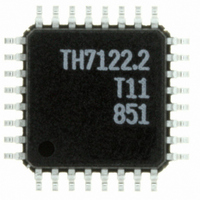
TH7122ENE Melexis Inc, TH7122ENE Datasheet - Page 12

TH7122ENE
Manufacturer Part Number
TH7122ENE
Description
IC TXRX 930MHZ FSK/FM/ASK 32LQFP
Manufacturer
Melexis Inc
Specifications of TH7122ENE
Frequency
300MHz ~ 930MHz
Data Rate - Maximum
115Kbps
Modulation Or Protocol
ASK, FM, FSK
Applications
Alarm and Security Systems, RKE, TPMS
Power - Output
-10dBm ~ 11dBm
Sensitivity
-105dBm
Voltage - Supply
2.2 V ~ 5.5 V
Current - Receiving
14mA
Current - Transmitting
23mA @ 10dBm
Data Interface
PCB, Surface Mount
Antenna Connector
PCB, Surface Mount
Operating Temperature
-40°C ~ 85°C
Package / Case
32-LQFP
Transmitting Current
12mA
Data Rate
115Kbps
Frequency Range
300MHz To 930MHz
Modulation Type
AM, FM, FSK
Sensitivity Dbm
-105dBm
Rf Ic Case Style
LQFP
No. Of Pins
32
Supply Voltage
RoHS Compliant
Output Power
10dBm
Rohs Compliant
Yes
Lead Free Status / RoHS Status
Lead free / RoHS Compliant
Memory Size
-
Lead Free Status / RoHS Status
Lead free / RoHS Compliant
Other names
TH7122.3
TH7122ENETR
TH7122ENETR
Available stocks
Company
Part Number
Manufacturer
Quantity
Price
3.1.5
The phase-frequency detector creates an error voltage proportional to the phase difference between the
reference signal f
is very useful because it decreases the acquisition time significantly. The gain of the phase detector can be
expressed as:
where I
frequency control characteristic is with negative polarity. This means the VCO frequency increases if the loop
filter output voltage decreases and vice versa. When an external varactor diode is added to the VCO tank,
the tuning characteristic can be changed between positive and negative depending on the particular varactor
diode circuitry. Therefore the PDFPOL register can be used to define the phase detector polarity.
3.1.6
In Programmable User Mode a lock-detect signal LD is available at pin FS1/LD (pin 19). The lock detection
circuitry uses Up and Down signals from the phase detector to check them for phase coherency. Figure 4
shows an overview of the lock signal generation. The locked state and the unlock condition will be decided
on the register settings of LDTM and ERTM respectively. In the start-up phase of the PLL, Up and Down
signals are quite unbalanced and counter CNT_LD receives no clock signal. When the loop approaches
steady state, the signals Up and Down begin to overlap and CNT_LD counts down. Herein register LDTM
sets the number of counts which are necessary to set the lock detection signal LD. If an unlock condition
occurs, the counter CNT_LD will be reloaded and therefore its CARRY falls back.
39010 07122
Rev. 010
frequency f
3.0000MHz
3.0000MHz
8.0000MHz
8.0000MHz
8.0000MHz
Crystal
CP
ERTM [1 : 0]
Phase-Frequency Detector
Lock Detector
LDTM [1 : 0]
is the charge pump current which is set via register CPCUR. In the TH7122 design the VCO
PFD
RO
Down
RO
F
Up
R
RO
and f
N
2
2
. The implementation of the phase detector is a phase-frequency type. That circuitry
resolution f
Frequency
2.93kHz
2.93kHz
12.5kHz
&
=
250kHz
25kHz
K
PD
=
I
2
R
CP
π
&
&
,
Page 12 of 44
counter
D
CR
LOAD
D
CR
LOAD
1023
1023
640
320
CNT_ER
32
CNT_LD
R
CARRY
CARRY
FSK/FM/ASK Transceiver
counter
131071
RESET LD
13107
35812
34746
3660
Control
Logic
N
Fig. 4:
S
R
Q
(7)
Lock Detection Circuit
27 to 930MHz
TH7122
LOCKMODE
frequency f
384.372MHz
38.437MHz
447.65MHz
868.65MHz
Operating
915.0MHz
MUX
Data Sheet
Feb/09
VCO
LD


