EM250-BBRD-R Ember, EM250-BBRD-R Datasheet - Page 26
EM250-BBRD-R
Manufacturer Part Number
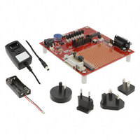
EM250-BBRD-R
Description
EM250 BREAKOUT BOARD
Manufacturer
Ember
Type
Transceiver, 802.15.4r
Datasheet
1.EM250-RCM-R.pdf
(126 pages)
Specifications of EM250-BBRD-R
Frequency
2.4GHz
For Use With/related Products
EM250
Lead Free Status / RoHS Status
Lead free / RoHS Compliant
Other names
636-1024


EM250
4.14 Sleep Timer
4.15 Power Management
120-0082-000S
The 16-bit sleep timer is contained in the always-powered digital block. It has the following features:
The clock source for the sleep timer can be either the 32.768 kHz clock or the calibrated 1kHz clock (see
Table 15). After choosing the clock source, the frequency is slowed down with a 2
final timer clock (see Table 16). Legal values for N are 0 to 10. The slowest rate the sleep timer counter wraps
is 2
The EmberZNet software allows the application to define the clock source and prescaler value. Therefore, a
programmable sleep/wake duty cycle can be configured according to the application requirements.
The EM250 supports three different power modes: processor ACTIVE, processor IDLE, and DEEP SLEEP.
The IDLE power mode stops code execution of the XAP2b until any interrupt occurs or an external SIF wakeup
command is seen. All peripherals of the EM250 including the radio continue to operate normally.
The DEEP SLEEP power mode powers off most of the EM250 but leaves the critical chip functions, such as the
GPIO pads and RAM powered by the High Voltage Supply (VDD_PADS). The EM250 can be woken by configuring
the sleep timer to generate an interrupt after a period of time, using an external interrupt, or with the SIF in-
terface. Activity on a serial interface may also be configured to wake the EM250, though actual reception of
data is not re-enabled until the EM250 has finished waking up. Depending on the speed of the serial data, it is
possible to finish waking up in the middle of a byte. Care must be taken to reset the serial interface between
bytes and discard any garbage data before the rest. Another condition for wakeup is general activity on GPIO
pins. The GPIO activity monitoring is described in section 5.1.
When in DEEP SLEEP, the internal regulator is disabled and VREG_OUT is turned off. All GPIO output signals
are maintained in a frozen state. Additionally, the state of all registers in the powered-down low-voltage do-
main of the EM250 is lost. Register settings for application peripherals should be preserved by the application
as desired. The operation of DEEP SLEEP is controlled by EmberZNet APIs which automatically preserve the
state of necessary system peripherals. The internal XAP2b CPU registers are automatically saved and restored
to RAM by hardware when entering and leaving the DEEP SLEEP mode, allowing code execution to continue
from where it left off. The event that caused the wakeup and any additional events that occurred while wak-
ing up are reported to the application via the EmberZNet APIs. Upon waking from DEEP SLEEP, the internal
regulator is re-enabled.
CLK_DIV[3:0]
16
N = 11..15
CLK_SEL
Two output compare registers, with interrupts
Only Compare A Interrupt generates Wake signal
Further clock divider of 2
N = 0..10
* 2
10
0
1
/ 1kHz ≈ 67109 sec. ≈ about 1118.48 min. ≈ 18.6 hrs.
Clock Source
Calibrated 1kHz clock
32.768kHz clock
Clock Source Prescale Factor
2
2
N
10
N
, for N = 0 to 10
Table 16. Sleep Timer Clock Source Prescaling
Table 15. Sleep Timer Clock Source Selection
Page 26
N
prescaler to generate the
Related parts for EM250-BBRD-R
Image
Part Number
Description
Manufacturer
Datasheet
Request
R

Part Number:
Description:
IC ZIGBEE SYSTEM-ON-CHIP 48-QFN
Manufacturer:
Ember
Datasheet:

Part Number:
Description:
KIT JUMP START FOR EM250
Manufacturer:
Ember
Datasheet:

Part Number:
Description:
KIT EVAL EM250 RF TEST
Manufacturer:
Ember
Datasheet:

Part Number:
Description:
EM250 RCM BOARD
Manufacturer:
Ember
Datasheet:

Part Number:
Description:
KIT DEV FOR EM250
Manufacturer:
Ember
Datasheet:

Part Number:
Description:
KIT DEV EMBER ZIGBEE W/PCWH
Manufacturer:
Custom Computer Services Inc (CCS)

Part Number:
Description:
PROGRAMMER USB FLASH EM250/260
Manufacturer:
Ember
Datasheet:

Part Number:
Description:
IC ZIGBEE SYSTEM-ON-CHIP 40-QFN
Manufacturer:
Ember
Datasheet:
Part Number:
Description:
IC RF TXRX ZIGBEE 128KB 48QFN
Manufacturer:
Ember
Datasheet:
Part Number:
Description:
IC RF TXRX ZIGBEE 192KB 48QFN
Manufacturer:
Ember
Datasheet:

Part Number:
Description:
INSIGHT ADAPTER FOR EM2XX
Manufacturer:
Ember
Datasheet:

Part Number:
Description:
IAR EWARM LICENCE FOR EM35X
Manufacturer:
Ember
Datasheet:

Part Number:
Description:
INSIGHT ADAPTER 3 FOR EM35X
Manufacturer:
Ember
Datasheet:

Part Number:
Description:
EM35X BREAKOUT BOARD
Manufacturer:
Ember
Datasheet:

Part Number:
Description:
EM260 RCM BOARD
Manufacturer:
Ember
Datasheet: