C8051F523A-IM Silicon Laboratories Inc, C8051F523A-IM Datasheet - Page 65
C8051F523A-IM
Manufacturer Part Number
C8051F523A-IM
Description
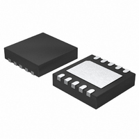
IC 8051 MCU 4K FLASH 10DFN
Manufacturer
Silicon Laboratories Inc
Series
C8051F52xr
Specifications of C8051F523A-IM
Program Memory Type
FLASH
Program Memory Size
4KB (4K x 8)
Package / Case
10-DFN
Core Processor
8051
Core Size
8-Bit
Speed
25MHz
Connectivity
LIN, SPI, UART/USART
Peripherals
Brown-out Detect/Reset, POR, PWM, Temp Sensor, WDT
Number Of I /o
6
Ram Size
256 x 8
Voltage - Supply (vcc/vdd)
1.8 V ~ 5.25 V
Data Converters
A/D 6x12b
Oscillator Type
Internal
Operating Temperature
-40°C ~ 125°C
Processor Series
C8051F5x
Core
8051
Data Bus Width
8 bit
Data Ram Size
256 B
Interface Type
SPI/UART
Maximum Clock Frequency
25 MHz
Number Of Programmable I/os
6
Number Of Timers
3
Maximum Operating Temperature
+ 125 C
Mounting Style
SMD/SMT
3rd Party Development Tools
PK51, CA51, A51, ULINK2
Development Tools By Supplier
C8051F500DK
Minimum Operating Temperature
- 40 C
On-chip Adc
6-ch x 12-bit
Lead Free Status / RoHS Status
Lead free / RoHS Compliant
For Use With
336-1488 - KIT DEV C8051F53XA, C8051F52XA770-1006 - ISP 4PORT FOR SILABS C8051F MCU336-1455 - ADAPTER PROGRAM TOOLSTICK F520
Eeprom Size
-
Lead Free Status / Rohs Status
Lead free / RoHS Compliant
Other names
336-1491-5


SFR Definition 4.5. ADC0CF: ADC0 Configuration
Note: Round the result up.
Bits7–3: AD0SC4–0: ADC0 SAR Conversion Clock Period Bits.
Bits2–1: AD0RPT1–0: ADC0 Repeat Count.
Bit0:
R/W
Bit7
SAR Conversion clock is derived from FCLK by the following equation, where AD0SC refers
to the 5-bit value held in bits AD0SC4–0. SAR Conversion clock requirements are given in
Table 2.3 on page 29.
BURSTEN = 0: FCLK is the current system clock.
BURSTEN = 1: FCLK is the Burst Mode Oscillator, specified in Table 2.3.
Controls the number of conversions taken and accumulated between ADC0 End of
Conversion (ADCINT) and ADC0 Window Comparator (ADCWINT) interrupts. A convert
start is required for each conversion unless Burst Mode is enabled. In Burst Mode, a single
convert start can initiate multiple self-timed conversions. Results in both modes are
accumulated in the ADC0H:ADC0L register. When AD0RPT1–0 are set to a value other
than '00', the AD0LJST bit in the ADC0CN register must be set to '0' (right justified).
00: 1 conversion is performed.
01: 4 conversions are performed and accumulated.
10: 8 conversions are performed and accumulated.
11: 16 conversions are performed and accumulated.
GAINEN: Gain Enable Bit.
Controls the gain programming. For more information of the usage, refer to the following
chapter: Section “4.4. Selectable Gain” on page 60.
AD0SC
R/W
Bit6
=
------------------- - 1
CLK
AD0SC
FCLK
R/W
Bit5
SAR
–
*
R/W
Bit4
C8051F52x/F52xA/F53x/F53xA
or
Rev. 1.3
R/W
Bit3
CLK
SAR
R/W
Bit2
=
AD0RPT
----------------------------
AD0SC
FCLK
R/W
Bit1
+
1
GAINEN
R/W
Bit0
SFR Address:
Reset Value
11111000
0xBC
65
Related parts for C8051F523A-IM
Image
Part Number
Description
Manufacturer
Datasheet
Request
R

Part Number:
Description:
SMD/C°/SINGLE-ENDED OUTPUT SILICON OSCILLATOR
Manufacturer:
Silicon Laboratories Inc
Part Number:
Description:
Manufacturer:
Silicon Laboratories Inc
Datasheet:
Part Number:
Description:
N/A N/A/SI4010 AES KEYFOB DEMO WITH LCD RX
Manufacturer:
Silicon Laboratories Inc
Datasheet:
Part Number:
Description:
N/A N/A/SI4010 SIMPLIFIED KEY FOB DEMO WITH LED RX
Manufacturer:
Silicon Laboratories Inc
Datasheet:
Part Number:
Description:
N/A/-40 TO 85 OC/EZLINK MODULE; F930/4432 HIGH BAND (REV E/B1)
Manufacturer:
Silicon Laboratories Inc
Part Number:
Description:
EZLink Module; F930/4432 Low Band (rev e/B1)
Manufacturer:
Silicon Laboratories Inc
Part Number:
Description:
I°/4460 10 DBM RADIO TEST CARD 434 MHZ
Manufacturer:
Silicon Laboratories Inc
Part Number:
Description:
I°/4461 14 DBM RADIO TEST CARD 868 MHZ
Manufacturer:
Silicon Laboratories Inc
Part Number:
Description:
I°/4463 20 DBM RFSWITCH RADIO TEST CARD 460 MHZ
Manufacturer:
Silicon Laboratories Inc
Part Number:
Description:
I°/4463 20 DBM RADIO TEST CARD 868 MHZ
Manufacturer:
Silicon Laboratories Inc
Part Number:
Description:
I°/4463 27 DBM RADIO TEST CARD 868 MHZ
Manufacturer:
Silicon Laboratories Inc
Part Number:
Description:
I°/4463 SKYWORKS 30 DBM RADIO TEST CARD 915 MHZ
Manufacturer:
Silicon Laboratories Inc
Part Number:
Description:
N/A N/A/-40 TO 85 OC/4463 RFMD 30 DBM RADIO TEST CARD 915 MHZ
Manufacturer:
Silicon Laboratories Inc
Part Number:
Description:
I°/4463 20 DBM RADIO TEST CARD 169 MHZ
Manufacturer:
Silicon Laboratories Inc