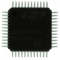
C8051F344-GQ Silicon Laboratories Inc, C8051F344-GQ Datasheet - Page 35

C8051F344-GQ
Manufacturer Part Number
C8051F344-GQ
Description
IC 8051 MCU FLASH 64K 48TQFP
Manufacturer
Silicon Laboratories Inc
Series
C8051F34xr
Datasheets
1.C8051F349-GQ.pdf
(276 pages)
2.C8051F344-GQ.pdf
(1 pages)
3.C8051F347-GQ.pdf
(296 pages)
Specifications of C8051F344-GQ
Program Memory Type
FLASH
Program Memory Size
64KB (64K x 8)
Package / Case
48-TQFP, 48-VQFP
Core Processor
8051
Core Size
8-Bit
Speed
25MHz
Connectivity
EBI/EMI, SMBus (2-Wire/I²C), SPI, UART/USART, USB
Peripherals
Brown-out Detect/Reset, POR, PWM, Temp Sensor, WDT
Number Of I /o
40
Ram Size
4.25K x 8
Voltage - Supply (vcc/vdd)
2.7 V ~ 3.6 V
Data Converters
A/D 20x10b
Oscillator Type
Internal
Operating Temperature
-40°C ~ 85°C
Processor Series
C8051F3x
Core
8051
Data Bus Width
8 bit
Data Ram Size
5.25 KB
Interface Type
I2C/SMBus/SPI/UART/USB
Maximum Clock Frequency
25 MHz
Number Of Programmable I/os
40
Number Of Timers
4
Operating Supply Voltage
2.7 V to 5.25 V
Maximum Operating Temperature
+ 85 C
Mounting Style
SMD/SMT
3rd Party Development Tools
KSK-SL-F34X, KSK-SL-TOOLSTICK, PK51, CA51, A51, ULINK2
Development Tools By Supplier
C8051F340DK
Minimum Operating Temperature
- 40 C
On-chip Adc
17-ch x 10-bit
No. Of I/o's
40
Ram Memory Size
4352Byte
Cpu Speed
25MHz
No. Of Timers
4
Rohs Compliant
Yes
Package
48TQFP
Device Core
8051
Family Name
C8051F34x
Maximum Speed
25 MHz
Lead Free Status / RoHS Status
Lead free / RoHS Compliant
For Use With
336-1748 - ADAPTER TOOLSTICK FOR C8051F34X770-1006 - ISP 4PORT FOR SILABS C8051F MCU336-1452 - ADAPTER PROGRAM TOOLSTICK F340
Eeprom Size
-
Lead Free Status / Rohs Status
Lead free / RoHS Compliant
Other names
336-1302
Available stocks
Company
Part Number
Manufacturer
Quantity
Price
Company:
Part Number:
C8051F344-GQ
Manufacturer:
SiliconL
Quantity:
1 943
Company:
Part Number:
C8051F344-GQ
Manufacturer:
Silicon Laboratories Inc
Quantity:
10 000
Company:
Part Number:
C8051F344-GQR
Manufacturer:
Silicon Laboratories Inc
Quantity:
10 000
- Current page: 35 of 296
- Download datasheet (3Mb)
1.9.
The C8051F340/1/2/3/4/5/6/7 devices include an on-chip 10-bit SAR ADC with a true differential input mul-
tiplexer. With a maximum throughput of 200 ksps, the ADC offers true 10-bit linearity with an INL of ±1LSB.
The ADC system includes a configurable analog multiplexer that selects both positive and negative ADC
inputs. Twenty (48-pin package) or twenty-one (32-pin package) of the Port I/O pins can be used as analog
inputs to the ADC. Additionally, the on-chip Temperature Sensor output and the power supply voltage
(V
Conversions can be started in six ways: a software command, an overflow of Timer 0, 1, 2, or 3, or an
external convert start signal. This flexibility allows the start of conversion to be triggered by software
events, a periodic signal (timer overflows), or external HW signals. Conversion completions are indicated
by a status bit and an interrupt (if enabled). The resulting 10-bit data word is latched into the ADC data
SFRs upon completion of a conversion.
Window compare registers for the ADC output data can be configured to interrupt the controller when ADC
data is either within or outside of a specified range. The ADC can monitor a key voltage continuously in
background mode, but not interrupt the controller unless the converted data is within/outside the specified
range.
* 21 Selections on 32-pin package
DD
20 Selections on 48-pin package
Port I/O
Port I/O
) are available as ADC inputs. User firmware may shut down the ADC to save power.
Sensor
VREF
Pins*
Pins*
Temp
GND
VDD
10-Bit Analog to Digital Converter
Analog Multiplexer
Negative
Positive
(AIN+)
AMUX
AMUX
(AIN-)
Input
Input
Figure 1.12. 10-Bit ADC Block Diagram
Configuration, Control, and Data Registers
C8051F340/1/2/3/4/5/6/7/8/9
Rev. 1.1
(+)
(-)
ADC
10-Bit
SAR
End of
Conversion
Interrupt
Conversion
Start
Window Compare
16
Logic
100
000
001
010
011
101
ADC Data
AD0BUSY (W)
Timer 0 Overflow
Timer 2 Overflow
Timer 1 Overflow
CNVSTR Input
Timer 3 Overflow
Registers
Window
Compare
Interrupt
35
Related parts for C8051F344-GQ
Image
Part Number
Description
Manufacturer
Datasheet
Request
R
Part Number:
Description:
SMD/C°/SINGLE-ENDED OUTPUT SILICON OSCILLATOR
Manufacturer:
Silicon Laboratories Inc
Part Number:
Description:
Manufacturer:
Silicon Laboratories Inc
Datasheet:
Part Number:
Description:
N/A N/A/SI4010 AES KEYFOB DEMO WITH LCD RX
Manufacturer:
Silicon Laboratories Inc
Datasheet:
Part Number:
Description:
N/A N/A/SI4010 SIMPLIFIED KEY FOB DEMO WITH LED RX
Manufacturer:
Silicon Laboratories Inc
Datasheet:
Part Number:
Description:
N/A/-40 TO 85 OC/EZLINK MODULE; F930/4432 HIGH BAND (REV E/B1)
Manufacturer:
Silicon Laboratories Inc
Part Number:
Description:
EZLink Module; F930/4432 Low Band (rev e/B1)
Manufacturer:
Silicon Laboratories Inc
Part Number:
Description:
I°/4460 10 DBM RADIO TEST CARD 434 MHZ
Manufacturer:
Silicon Laboratories Inc
Part Number:
Description:
I°/4461 14 DBM RADIO TEST CARD 868 MHZ
Manufacturer:
Silicon Laboratories Inc
Part Number:
Description:
I°/4463 20 DBM RFSWITCH RADIO TEST CARD 460 MHZ
Manufacturer:
Silicon Laboratories Inc
Part Number:
Description:
I°/4463 20 DBM RADIO TEST CARD 868 MHZ
Manufacturer:
Silicon Laboratories Inc
Part Number:
Description:
I°/4463 27 DBM RADIO TEST CARD 868 MHZ
Manufacturer:
Silicon Laboratories Inc
Part Number:
Description:
I°/4463 SKYWORKS 30 DBM RADIO TEST CARD 915 MHZ
Manufacturer:
Silicon Laboratories Inc
Part Number:
Description:
N/A N/A/-40 TO 85 OC/4463 RFMD 30 DBM RADIO TEST CARD 915 MHZ
Manufacturer:
Silicon Laboratories Inc
Part Number:
Description:
I°/4463 20 DBM RADIO TEST CARD 169 MHZ
Manufacturer:
Silicon Laboratories Inc


