ST203C686MAJ03 AVX Corporation, ST203C686MAJ03 Datasheet - Page 46
ST203C686MAJ03
Manufacturer Part Number
ST203C686MAJ03
Description
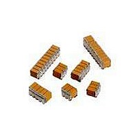
CAP CER 68UF 25V STACKED SMD
Manufacturer
AVX Corporation
Series
TurboCap™r
Specifications of ST203C686MAJ03
Capacitance
68µF
Tolerance
±20%
Temperature Coefficient
X7R
Voltage - Rated
25V
Mounting Type
Surface Mount, MLCC
Operating Temperature
-55°C ~ 125°C
Features
Stacked
Applications
Filtering Switch Mode Power Supplies
Package / Case
6-Stacked SMD, J-Lead
Size / Dimension
0.325" L x 0.300" W (8.26mm x 7.62mm)
Thickness
5.59mm Max
Lead Style
J-Lead
Voltage Rating
25 Volts
Operating Temperature Range
- 55 C to + 125 C
Product
General Type MLCCs
Dielectric Characteristic
X7R
Capacitance Tolerance
± 20%
Capacitor Case Style
DIP
No. Of Pins
6
Capacitor Mounting
SMD
Rohs Compliant
No
Termination Style
Radial
Lead Spacing
6.35 mm
Dimensions
7.62 mm W x 8.26 mm L x 5.59 mm H
Dissipation Factor Df
2.5
Lead Free Status / RoHS Status
Contains lead / RoHS non-compliant
Ratings
-
Lead Spacing
-
Lead Free Status / RoHS Status
Contains lead / RoHS non-compliant
Other names
478-6117


TurboCap
High-CV SMPS Capacitors
ELECTRICAL SPECIFICATIONS
Temperature Coefficient
Temperature Coefficient
Capacitance Test (MIL-STD-202 Method 305)
25°C, 1.0±0.2 Vrms (open circuit voltage) at 1KHz
Dissipation Factor 25°C
2.5% Max @ 25°C, 1.0±0.2 Vrms (open circuit voltage) at 1KHz
Insulation Resistance 25°C (MIL-STD-202 Method 302)
500 MΩ-μF, whichever is less.
Insulation Resistance 125°C (MIL-STD-202 Method 302)
50 MΩ-μF, whichever is less.
HOW TO ORDER
CAPACITANCE (μF)
ST12
Cap (μF)
Style
ST12
ST20
AVX
100
220
.82
1.3
2.7
8.2
12
14
18
22
27
47
50
68
100V = 1
Voltage
25V = 3
50V = 5
5
...03
...05
...10
50V
Temperature
Coefficient
X7R = C
TM
±15%, -55° to +125°C
C
ST12
100V
...03
...05
...10
Capacitance Code
(2 significant digits
100 μF = 107
+ no. of zeros)
10 μF = 106
1 μF = 105
186
Voltage
...03
...05
...10
25V
Capacitance
Tolerance
M = ±20%
Dielectric Withstanding Voltage 25°C (Flash Test)
250% rated voltage for 5 seconds with 50 mA max charging current.
Life Test (1000 hrs)
X7R: 150% rated voltage at +125°C.
Moisture Resistance (MIL-STD-202 Method 106)
Ten cycles with no voltage applied.
Thermal Shock (MIL-STD-202 Method 107, Condition A)
Immersion Cycling (MIL-STD-202 Method 104, Condition B)
Resistance To Solder Heat (MIL-STD-202, Method 210,
M
Condition B, for 20 seconds)
...03
...05
...10
50V
ESR @ 10KHz
ESR @ 50KHz
ESR @ 100KHz
Typical ESR Performance (Ω)
A = Standard
ST20
Test Level
A
100V
...03
...05
...10
AVX Styles: ST12 and ST20
N = Straight Lead
J = Leads formed in
L = Leads formed out
0.007
0.003
0.002
27μF
Termination
N
500V
0.0015
0.004
0.002
47μF
Numbers inside
shaded areas refer
to the number of
leads per side (the
last two digits of
the part number.
of Leads
Per Side
Number
Development
03 = 3
05 = 5
10 = 10
03
0.0015
100μF
0.003
0.001
45
Related parts for ST203C686MAJ03
Image
Part Number
Description
Manufacturer
Datasheet
Request
R

Part Number:
Description:
Inverter Grade Thyristors
Manufacturer:
International Rectifier Corp.
Datasheet:

Part Number:
Description:
Manufacturer:
AVX Corporation
Datasheet:
Part Number:
Description:
Manufacturer:
AVX Corporation
Datasheet:
Part Number:
Description:
Manufacturer:
AVX Corporation
Datasheet:
Part Number:
Description:
Manufacturer:
AVX Corporation
Datasheet: