ST203C686MAJ03 AVX Corporation, ST203C686MAJ03 Datasheet - Page 13
ST203C686MAJ03
Manufacturer Part Number
ST203C686MAJ03
Description
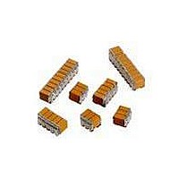
CAP CER 68UF 25V STACKED SMD
Manufacturer
AVX Corporation
Series
TurboCap™r
Specifications of ST203C686MAJ03
Capacitance
68µF
Tolerance
±20%
Temperature Coefficient
X7R
Voltage - Rated
25V
Mounting Type
Surface Mount, MLCC
Operating Temperature
-55°C ~ 125°C
Features
Stacked
Applications
Filtering Switch Mode Power Supplies
Package / Case
6-Stacked SMD, J-Lead
Size / Dimension
0.325" L x 0.300" W (8.26mm x 7.62mm)
Thickness
5.59mm Max
Lead Style
J-Lead
Voltage Rating
25 Volts
Operating Temperature Range
- 55 C to + 125 C
Product
General Type MLCCs
Dielectric Characteristic
X7R
Capacitance Tolerance
± 20%
Capacitor Case Style
DIP
No. Of Pins
6
Capacitor Mounting
SMD
Rohs Compliant
No
Termination Style
Radial
Lead Spacing
6.35 mm
Dimensions
7.62 mm W x 8.26 mm L x 5.59 mm H
Dissipation Factor Df
2.5
Lead Free Status / RoHS Status
Contains lead / RoHS non-compliant
Ratings
-
Lead Spacing
-
Lead Free Status / RoHS Status
Contains lead / RoHS non-compliant
Other names
478-6117


SMPS Stacked MLC Capacitors
(SM Style) SM Military Styles MIL-PRF-49470/1
MIL-PRF-49470/1
MIL-PRF-49470/1 - capacitor, fixed, ceramic dielectric, switch mode power supply (general purpose and temperature stable),
standard reliability and high reliability unencapsulated, Style PS01.
DIMENSIONS:
NOTES:
1. Dimensions are in millimeters (inches)
2. Unless otherwise specified, tolerances are 0.254 (±0.010).
3. Lead frame configuration is shown as typical above the seating plane.
4. See table I of MIL-PRF-49470/1 for specific maximum A dimension. For maximum B dimension, add 1.65 (0.065) to
5. For case code 5, dimensions shall be 2.54 (0.100) maximum and 0.305 (0.012) minimum.
6. Lead alignment within pin rows shall be within ±0.10 (0.005).
12
0.635 (0.025) MIN
2.54 (0.100) MAX
6.35 (0.250) MIN
(See Note 5)
the appropriate A dimension. For all lead styles, the number of chips is determined by the capacitance and voltage
rating.
Case Code
L
Note 4
LEAD STYLE J AND C
See
2.54 (0.100) TYP
B
1
2
3
4
5
6
1.27 (0.050) MIN
Note 4
See
0.254 (0.010)
RAD (TYP)
A
C
E
C ±0.635 (±0.025)
11.4 (0.450)
20.3 (0.800)
11.4 (0.450)
10.2 (0.400)
6.35 (0.250)
31.8 (1.250)
D
(0.020 ±0.002)
0.508 ±0.050
(0.055 ±0.010)
1.397 ±0.254
SEATING PLANE
See Note 3
See Note 6
49.5 (1.950)
36.8 (1.450)
24.1 (0.950)
8.89 (0.350)
6.20 (0.224)
49.5 (1.950)
CIRCUIT DIAGRAM
Min.
D
52.7 (2.075)
40.0 (1.535)
27.3 (1.075)
10.8 (0.425)
6.97 (0.275)
52.7 (2.075)
Max.
6.35 (0.250)
MIN
L
LEAD STYLE N AND A
LEAD STYLE L AND B
(0.010 ±0.002)
1.27 (0.050) MIN
0.254 ±0.05
12.7 (0.500)
22.1 (0.870)
12.7 (0.500)
11.2 (0.440)
7.62 (0.300)
34.3 (1.350)
E (max.)
C
E
C
E
millimeters (inches)
0.254 (0.010)
Number of
RAD (TYP)
per side
Leads
20
15
10
20
4
3
Related parts for ST203C686MAJ03
Image
Part Number
Description
Manufacturer
Datasheet
Request
R

Part Number:
Description:
Inverter Grade Thyristors
Manufacturer:
International Rectifier Corp.
Datasheet:

Part Number:
Description:
Manufacturer:
AVX Corporation
Datasheet:
Part Number:
Description:
Manufacturer:
AVX Corporation
Datasheet:
Part Number:
Description:
Manufacturer:
AVX Corporation
Datasheet:
Part Number:
Description:
Manufacturer:
AVX Corporation
Datasheet: