ST203C686MAJ03 AVX Corporation, ST203C686MAJ03 Datasheet - Page 111
ST203C686MAJ03
Manufacturer Part Number
ST203C686MAJ03
Description
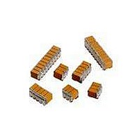
CAP CER 68UF 25V STACKED SMD
Manufacturer
AVX Corporation
Series
TurboCap™r
Specifications of ST203C686MAJ03
Capacitance
68µF
Tolerance
±20%
Temperature Coefficient
X7R
Voltage - Rated
25V
Mounting Type
Surface Mount, MLCC
Operating Temperature
-55°C ~ 125°C
Features
Stacked
Applications
Filtering Switch Mode Power Supplies
Package / Case
6-Stacked SMD, J-Lead
Size / Dimension
0.325" L x 0.300" W (8.26mm x 7.62mm)
Thickness
5.59mm Max
Lead Style
J-Lead
Voltage Rating
25 Volts
Operating Temperature Range
- 55 C to + 125 C
Product
General Type MLCCs
Dielectric Characteristic
X7R
Capacitance Tolerance
± 20%
Capacitor Case Style
DIP
No. Of Pins
6
Capacitor Mounting
SMD
Rohs Compliant
No
Termination Style
Radial
Lead Spacing
6.35 mm
Dimensions
7.62 mm W x 8.26 mm L x 5.59 mm H
Dissipation Factor Df
2.5
Lead Free Status / RoHS Status
Contains lead / RoHS non-compliant
Ratings
-
Lead Spacing
-
Lead Free Status / RoHS Status
Contains lead / RoHS non-compliant
Other names
478-6117


B
INCLUDING DRAFT CONCENTRIC AROUND B
MLC Chips
Packaging of Chip Components
B
8mm, 12mm & 24mm Embossed Tape
Metric Dimensions Will Govern
CONSTANT DIMENSIONS
VARIABLE DIMENSIONS
NOTES:
1. The cavity defined by A
S
Tape Size
1
1
1
Surround the component with sufficient clearance such that:
IS FOR TAPE READER REFERENCE ONLY
Double
12mm
12mm
24mm
Tape Size
8mm
Pitch
12mm
24mm
a) the component does not protrude beyond the sealing plane of the cover tape.
b) the component can be removed from the cavity in a vertical direction without mechanical
c) rotation of the component is limited to 20º maximum (see Sketches D & E).
d) lateral movement of the component is restricted to 0.5mm maximum (see Sketch F).
8mm
restriction, after the cover tape has been removed.
Side or Front Sectional View
T
T
T
K
2
1
0
TOP COVER
(0.171)
(0.323)
(0.323)
(0.791)
20.10
Max.
DEFORMATION
BETWEEN
EMBOSSMENTS
4.35
8.20
8.20
TAPE
B
Sketch “D”
1
0
, B
(0.059
0
1.50
, and K
(0.039)
(0.059)
(0.059)
(0.059)
CENTER LINES
OF CAVITY
D
Min.
1.00
1.50
1.50
1.50
0
D
0
shall be configured to provide the following:
+0.10
-0.0
+0.004
-0.0
1
)
(0.246) (0.138 ± 0.002) (0.157 ± 0.004) (0.079 ± 0.002)
(0.404) (0.217 ± 0.002) (0.157 ± 0.004) (0.079 ± 0.002)
(0.404) (0.217 ± 0.002) (0.315 ± 0.004) (0.079 ± 0.002)
(0.876) (0.453 ± 0.004) (0.630 ± 0.004) (0.079 ± 0.004)
10.25
10.25
22.25
Min.
6.25
D
(0.069 ± 0.004) (0.157 ± 0.004)
110
E
0
1.75 ± 0.10
2
0
A
MAX. CAVITY
SIZE - SEE NOTE 1
0
E
1
3.50 ± 0.05
5.50 ± 0.05
5.50 ± 0.05
11.5 ± 0.10
B
P
0
1
0.50mm (0.020)
P
Component Lateral Movements
2
User Direction of Feed
F
Maximum
P
0
Top View, Sketch "F"
4.0 ± 0.10
10 PITCHES CUMULATIVE
TOLERANCE ON TAPE
±0.2mm (±0.008)
P
16.00 ± 0.10
EMBOSSMENT
4.00 ± 0.10
4.00 ± 0.10
8.00 ± 0.10
0
P
D
2.00 mm x 1.20 mm AND
LARGER (0.079 x 0.047)
1
E
F
1
1
FOR COMPONENTS
0.50mm (0.020)
E
2
2. Tape with or without components shall pass around radius “R” without damage.
3. Bar code labeling (if required) shall be on the side of the reel opposite the round sprocket holes.
4. B
Maximum
Refer to EIA-556.
W
1
S
(0.024)
dimension is a reference dimension for tape feeder clearance only.
1
0.60
2.00 ± 0.05
2.00 ± 0.05
2.00 ± 0.05
2.00 ± 0.10
Min.
P
2
See Note 2
T Max.
(0.024)
(0.984)
(1.181)
(1.181)
(1.181)
Min.
30.0
30.0
30.0
0.60
25.0
R
millimeters (inches)
(0.098)
(0.256)
(0.256)
(0.472)
12.00
Max.
Chip Orientation
2.50
6.50
6.50
T
2
(0.004)
Max.
0.10
T
Sketch “E”
1
Top View
(0.327)
(0.484)
(0.484)
(0.957)
Max.
8.30
12.3
12.3
24.3
millimeters (inches)
W
See Note 1
See Note 1
See Note 1
See Note 1
A
0
B
0
K
0
Related parts for ST203C686MAJ03
Image
Part Number
Description
Manufacturer
Datasheet
Request
R

Part Number:
Description:
Inverter Grade Thyristors
Manufacturer:
International Rectifier Corp.
Datasheet:

Part Number:
Description:
Manufacturer:
AVX Corporation
Datasheet:
Part Number:
Description:
Manufacturer:
AVX Corporation
Datasheet:
Part Number:
Description:
Manufacturer:
AVX Corporation
Datasheet:
Part Number:
Description:
Manufacturer:
AVX Corporation
Datasheet: