S216S02F Sharp Microelectronics, S216S02F Datasheet - Page 8
S216S02F
Manufacturer Part Number
S216S02F
Description
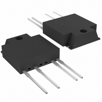
RELAY SSR 240VAC 16A ZC 4-SIP
Manufacturer
Sharp Microelectronics
Series
S216r
Datasheet
1.S216S02F.pdf
(13 pages)
Specifications of S216S02F
Load Current
16A
Circuit
SPST-NO (1 Form A)
Output Type
AC, Zero Cross
Voltage - Input
1.2VDC
Voltage - Load
0 ~ 240 V
Mounting Type
Through Hole
Termination Style
PC Pin
Package / Case
4-SIP
Control Voltage Type
DC
Input Voltage
1.4V
Load Voltage Range
80V To 240V
Switching Mode
Zero Cross
Load Current Rms Max
16A
Rms Load Voltage Max
600V
Surge Current
160A
Load Voltage Rating
35 V
Mounting Style
PCB
Relay Type
Solid State
Svhc
No SVHC (15-Dec-2010)
Rohs Compliant
Yes
Lead Free Status / RoHS Status
Lead free / RoHS Compliant
On-state Resistance
-
Lead Free Status / Rohs Status
Lead free / RoHS Compliant
Other names
425-2414
425-2414-5
425-2414-5
425-2414-5
425-2414-5
Available stocks
Company
Part Number
Manufacturer
Quantity
Price
Company:

Part Number:
S216S02F
Manufacturer:
LATTICE
Quantity:
1 300


■ Design Considerations
(
Output
∗
Operating temperature
) See Fig.2 about derating curve (I
Input
● Recommended Operating Conditions
● Design guide
In order for the SSR to turn off, the triggering current (l
When the input current (I
voltage across the Triac, V
please incorporate a snubber circuit. Due to the many different types of load that can be driven, we can
merely recommend some circuit vales to start with : Cs=0.1µF and Rs=47Ω. The operation of the SSR and
snubber circuit should be tested and if unintentional switching occurs, please adjust the snubber circuit com-
ponent values accordingly.
When making the transition from On to Off state, a snubber circuit should be used ensure that sudden drops
in current are not accompanied by large instantaneous changes in voltage across the Triac.
This fast change in voltage is brought about by the phase difference between current and voltage.
Primarily, this is experienced in driving loads which are inductive such as motors and solenoids.
Following the procedure outlined above should provide sufficient results.
For over voltage protection, a Varistor may be used.
Any snubber or Varistor used for the above mentioned scenarios should be located as close to the main out-
put triac as possible.
Particular attention needs to be paid when utilizing SSRs that incorporate zero crossing circuitry.
If the phase difference between the voltage and the current at the output pins is large enough, zero crossing
type SSRs cannot be used. The result, if zero crossing SSRs are used under this condition, is that the SSR
may not turn on and off irregardless of the input current. In this case, only a non zero cross type SSR should
be used in combination with the above mentioned snubber circuit selection process.
The load current should be within the bounds of derating curve. (Refer to Fig.2)
Also, please use the optional heat sink when necessary.
In case the optional heat sink is used and the isolation voltage between the device and the optional heat sink
is needed, please locate the insulation sheet between the device and the heat sink.
When the optional heat sink is equipped, please set up the M3 screw-fastening torque at 0.3 to 0.5N•m.
In order to dissipate the heat generated from the inside of device effectively, please follow the below sugges-
tions.
Input signal current at ON state
Input signal current at OFF state
Load supply voltage
Load supply current
Frequency
Parameter
T
(rms) vs. ambient temperature).
S116S02
S216S02
F
) is below 0.1mA, the output Triac will be in the open circuit mode. However, if the
D
, increases faster than rated dV/dt, the Triac may turn on. To avoid this situation,
V
I
I
OUT
Symbol
I
OUT
F
F
(OFF)
(ON)
T
(rms)
f
opr
(rms)
Locate snubber circuit between output terminals
8
(Cs=0.1µF, Rs=47Ω)
F
) must be 0.1mA or less.
Conditions
−
−
−
−
−
MIN.
−20
0.1
16
80
80
47
0
S116S02 Series
S216S02 Series
Sheet No.: D4-A02701EN
×80%(
I
MAX.
T
120
240
(rms)
0.1
24
63
80
∗
)
Unit
mA
mA
mA
Hz
˚C
V
Related parts for S216S02F
Image
Part Number
Description
Manufacturer
Datasheet
Request
R

Part Number:
Description:
IC FLASH 32MBIT 110NS 56SSOP
Manufacturer:
Sharp Microelectronics
Datasheet:

Part Number:
Description:
IC FLASH 16MBIT 100NS 56TSOP
Manufacturer:
Sharp Microelectronics
Datasheet:

Part Number:
Description:
IC FLASH 64MBIT 120NS 56TSOP
Manufacturer:
Sharp Microelectronics
Datasheet:

Part Number:
Description:
IC FLASH 16MBIT 90NS 48TSOP
Manufacturer:
Sharp Microelectronics
Datasheet:
Part Number:
Description:
IC SRAM 16KBIT 100NS 24DIP
Manufacturer:
Sharp Microelectronics
Datasheet:
Part Number:
Description:
IC SRAM 16KBIT 100NS 24SOP
Manufacturer:
Sharp Microelectronics
Datasheet:
Part Number:
Description:
IC SRAM 64KBIT 100NS 28DIP
Manufacturer:
Sharp Microelectronics
Datasheet:
Part Number:
Description:
IC SRAM 64KBIT 100NS 28SOP
Manufacturer:
Sharp Microelectronics
Datasheet:
Part Number:
Description:
IC SRAM 64KBIT 100NS 28SOP
Manufacturer:
Sharp Microelectronics
Datasheet:
Part Number:
Description:
IC SRAM 256KBIT 70NS 28DIP
Manufacturer:
Sharp Microelectronics
Datasheet:
Part Number:
Description:
IC FLASH 8MBIT 90NS 48TSOP
Manufacturer:
Sharp Microelectronics
Datasheet:
Part Number:
Description:
IC FLASH 8MBIT 85NS 40TSOP
Manufacturer:
Sharp Microelectronics
Datasheet:
Part Number:
Description:
IC FLASH 8MBIT 85NS 40TSOP
Manufacturer:
Sharp Microelectronics
Datasheet:
Part Number:
Description:
IC FLASH 16MBIT 90NS 48TSOP
Manufacturer:
Sharp Microelectronics
Datasheet:
Part Number:
Description:
IC FLASH 16MBIT 70NS 56TSOP
Manufacturer:
Sharp Microelectronics
Datasheet: