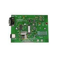
PG103003 Microchip Technology, PG103003 Datasheet - Page 9

PG103003
Manufacturer Part Number
PG103003
Description
KIT PROGRAMMERS MICROID 13.56MHZ
Manufacturer
Microchip Technology
Series
MicroID®r
Type
MicroID®r
Datasheet
1.PG103003.pdf
(22 pages)
Specifications of PG103003
Contents
Programmer, Power Supply, Cable(s) and Software
Product
RFID Kits
Lead Free Status / RoHS Status
Lead free / RoHS Compliant
For Use With/related Products
MCRF355, MCRF360
Lead Free Status / RoHS Status
Lead free / RoHS Compliant, Lead free / RoHS Compliant
3.0
The MCRF355 requires external coils and a capacitor
in order to resonate at the carrier frequency of the
reader. About one-fourth to one-half of the turns of the
coil should be connected between antenna B and V
remaining turns should be connected between antenna
A and B pads.
Figures 3-1 (a) and (b) show possible configurations of
the external circuits for the MCRF355. In Figure 3-1 (a),
two external antenna coils (L1 and L2) in series and a
capacitor that is connected across the two inductors
FIGURE 3-1:
© 2005 Microchip Technology Inc.
Interrogator
RESONANT CIRCUIT
Interrogator
Interrogator
CONFIGURATION OF EXTERNAL RESONANT CIRCUITS
Modulated
RF Carrier
RF Carrier
Modulated
RF Data
RF Data
(a)
(b)
C
L
L1
L2
L1 > L2
SS
;
C1
C2
C1
C2
Ant. A
Ant. B
V
SS
form a parallel resonant circuit to pick up incoming RF
signals and also to send modulated signals to the
reader. The first coil (L1) is connected between
antenna A and B pads. The second coil (L2) is con-
nected between antenna B and V
tor is connected between antenna A and V
Figure 3-1(b) shows the resonant circuit formed by two
capacitors (C1 and C2) and one inductor.
MCRF355
Ant. A
Ant. B
V
SS
MCRF355
Where:
L
L
T
M
f 0
= L
= Mutual inductance
f 0
=
=
between L
MCRF355
1
----------------------- -
2
------------------------------------------- -
2
+ L
SS
1
CL
L
2
⎛
⎝
pads. The capaci-
+ 2L
----------------------
C 1
T
DS21287G-page 9
1
C 1 C 2
1
+
and L
M
C 2
SS
⎞
⎠
pads.
2


