EVALPFC1-TDA 4863-2 Infineon Technologies, EVALPFC1-TDA 4863-2 Datasheet - Page 7
EVALPFC1-TDA 4863-2
Manufacturer Part Number
EVALPFC1-TDA 4863-2
Description
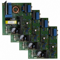
BOARD DEMO 160W DCM-PFC SMPS
Manufacturer
Infineon Technologies
Series
CoolMOS™r
Specifications of EVALPFC1-TDA 4863-2
Main Purpose
Power Management, Power Factor Correction
Embedded
No
Utilized Ic / Part
TDA4863-2
Primary Attributes
160 W, 400 V & 400 mA Out, 85~265 VAC In
Secondary Attributes
Totem Pole Output with Active Shutdown
Lead Free Status / RoHS Status
Lead free / RoHS Compliant
Other names
EVALPFC1-TDA4863-2IN


Pin Definitions and Functions
Pin
1
2
3
4
5
6
7
8
Version 2.1
Symbol
VSENSE Voltage Amplifier Inverting Input
VAOUT
MULTIN Multiplier Input
ISENSE
DETIN
GND
GTDRV
VCC
Description
VSENSE is connected via a resistive divider to the boost converter
output. With a capacitor connected to VAOUT the internal error
amplifier acts as an integrator.
Voltage Amplifier Output
V
overshoot the input voltage is clamped internally at 5 V. IfV
less then 2.2 V the gate driver is inhibited. If the current flowing into
this pin exceeds an internal threshold the multiplier output voltage is
reduced to prevent the MOSFET from overvoltage damage.
MULTIN is the second multiplier input and is connected via a resistive
divider to the rectifier output voltage.
Current Sense Input
ISENSE is connected to a sense resistor controlling the MOSFET
source current. The input is internally clamped at -0.3 V to prevent
negative input voltage interaction. A leading edge blanking circuitry
suppresses voltage spits when turning the MOSFET on.
Zero Current Detector Input
DETIN is connected to an auxiliary winding monitoring the zero
crossing of the inductor current.
Ground
Gate Driver Output
GTDRV is the output of a totem-pole circuitry for direct driving a
MOSFET. Compared with TDA4863 the TDA4863-2 can drive 20A
MOSFETS. To achieve this the gate output voltage V
been set to 0.85V. An active shutdown circuitry ensures that GTDRV
is set to low if the IC is switched off.
Positive Voltage Supply
If V
falls below the turn-off threshold the IC is switched off. In switch off
mode power consumption is very low. Two capacitors should be
connected to Vcc. An electrolytic capacitor and 100nF cermanic
capacitor which is used to absorb fast supply current spikes. Make
sure that the electrolytic capacitor is discharged before the IC is
plugged into the application board.
VAOUT
CC
excees the turn-on threshold the IC is switched on. When Vcc
is connected internally to the first multiplier input. To prevent
7
GTL
at I
TDA4863-2
GT
VAOUT
22 Feb 2005
Overview
=0A has
is
Related parts for EVALPFC1-TDA 4863-2
Image
Part Number
Description
Manufacturer
Datasheet
Request
R

Part Number:
Description:
Manufacturer:
Infineon Technologies AG
Datasheet:
Part Number:
Description:
Manufacturer:
Infineon Technologies AG
Datasheet:
Part Number:
Description:
Manufacturer:
Infineon Technologies AG
Datasheet:
Part Number:
Description:
Manufacturer:
Infineon Technologies AG
Datasheet:
Part Number:
Description:
Manufacturer:
Infineon Technologies AG
Datasheet:
Part Number:
Description:
Manufacturer:
Infineon Technologies AG
Datasheet:
Part Number:
Description:
Manufacturer:
Infineon Technologies AG
Datasheet:
Part Number:
Description:
16-bit microcontroller with 2x2 KByte RAM
Manufacturer:
Infineon Technologies AG
Datasheet:
Part Number:
Description:
NPN silicon RF transistor
Manufacturer:
Infineon Technologies AG
Datasheet:
Part Number:
Description:
NPN silicon RF transistor
Manufacturer:
Infineon Technologies AG
Datasheet:
Part Number:
Description:
NPN silicon RF transistor
Manufacturer:
Infineon Technologies AG
Datasheet:
Part Number:
Description:
NPN silicon RF transistor
Manufacturer:
Infineon Technologies AG
Datasheet:
Part Number:
Description:
Si-MMIC-amplifier in SIEGET 25-technologie
Manufacturer:
Infineon Technologies AG
Datasheet:
Part Number:
Description:
IGBT Power Module
Manufacturer:
Infineon Technologies AG
Datasheet:
Part Number:
Description:
IC for switching-mode power supplies
Manufacturer:
Infineon Technologies AG
Datasheet: