EVALPFC1-TDA 4863-2 Infineon Technologies, EVALPFC1-TDA 4863-2 Datasheet - Page 10
EVALPFC1-TDA 4863-2
Manufacturer Part Number
EVALPFC1-TDA 4863-2
Description
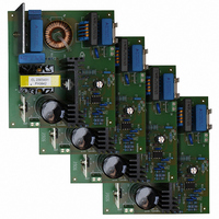
BOARD DEMO 160W DCM-PFC SMPS
Manufacturer
Infineon Technologies
Series
CoolMOS™r
Specifications of EVALPFC1-TDA 4863-2
Main Purpose
Power Management, Power Factor Correction
Embedded
No
Utilized Ic / Part
TDA4863-2
Primary Attributes
160 W, 400 V & 400 mA Out, 85~265 VAC In
Secondary Attributes
Totem Pole Output with Active Shutdown
Lead Free Status / RoHS Status
Lead free / RoHS Compliant
Other names
EVALPFC1-TDA4863-2IN


2.4
Because of the integrator´s low bandwidth fast changes of the output voltage can’t be
regulated within an adequate time. Fast output changes occur during initial start-up,
sudden load removal, or output arcing. While the integrator´s differential input voltage
remains zero during this fast changes a peak current is flowing through the external
capacitor into pin VAOUT. If this current exceeds an internal defined margin the
overvoltage regulator circuitry reduces the multiplier output voltage. As a result the on
time of the MOSFET is reduced.
2.5
The one quadrant multiplier regulates the gate driver with respect of the DC output
voltage and the AC half wave rectified input voltage. Both inputs are designed to achieve
good linearity over a wide dynamic range to represent an AC line free from distortion.
Special efforts are made to assure universal line applications with respect to a 90 to
270 V AC range.
The multiplier output is internally clamped at 1.3 V. So the MOSFET is protected against
critical operating during start up.
2.6
The source current of the MOS transistor is transferred into a sense voltage via the
external sense resistor. The multiplier output voltage is compared with this sense
voltage. Switch on time of the MOS transistor is determined by the comparison result.
To protect the current comparator input from negative pulses a current source is inserted
which sends current out of the ISENSE pin every time when V
below ground potential. An internal RC-filter is connected to the ISENSE pin which
smoothes the switch-on current spike. The remaining switch-on current spike is blanked
out via a leading edge blanking circuit with a blanking time of typ. 200 ns.
The RS Flip-Flop ensures that only one single switch-on and switch-off pulse appears at
the gate drive output during a given cycle (double pulse suppression).
2.7
The zero current detector senses the inductor current via an auxiliary winding and
ensures that the next on-time of the MOSFET is initiated immediately when the inductor
current has reached zero. This reduces the reverse recovery losses of the boost
converter diode to a miniumum. The MOSFET is switched off when the voltage drop of
the shunt resistor reaches the voltage level of the multiplier output. So the boost current
waveform has a triangular shape and there are no deadtime gaps between the cycles.
This leads to a continuous AC line current limiting the peak current to twice of the
average current.
Version 2.1
Overvoltage Regulator
Multiplier
Current Sense Comparator, LEB and RS Flip-Flop
Zero Current Detector
10
Functional Description
ISENSE
-signal is falling
TDA4863-2
22 Feb 2005
Related parts for EVALPFC1-TDA 4863-2
Image
Part Number
Description
Manufacturer
Datasheet
Request
R

Part Number:
Description:
Manufacturer:
Infineon Technologies AG
Datasheet:
Part Number:
Description:
Manufacturer:
Infineon Technologies AG
Datasheet:
Part Number:
Description:
Manufacturer:
Infineon Technologies AG
Datasheet:
Part Number:
Description:
Manufacturer:
Infineon Technologies AG
Datasheet:
Part Number:
Description:
Manufacturer:
Infineon Technologies AG
Datasheet:
Part Number:
Description:
Manufacturer:
Infineon Technologies AG
Datasheet:
Part Number:
Description:
Manufacturer:
Infineon Technologies AG
Datasheet:
Part Number:
Description:
16-bit microcontroller with 2x2 KByte RAM
Manufacturer:
Infineon Technologies AG
Datasheet:
Part Number:
Description:
NPN silicon RF transistor
Manufacturer:
Infineon Technologies AG
Datasheet:
Part Number:
Description:
NPN silicon RF transistor
Manufacturer:
Infineon Technologies AG
Datasheet:
Part Number:
Description:
NPN silicon RF transistor
Manufacturer:
Infineon Technologies AG
Datasheet:
Part Number:
Description:
NPN silicon RF transistor
Manufacturer:
Infineon Technologies AG
Datasheet:
Part Number:
Description:
Si-MMIC-amplifier in SIEGET 25-technologie
Manufacturer:
Infineon Technologies AG
Datasheet:
Part Number:
Description:
IGBT Power Module
Manufacturer:
Infineon Technologies AG
Datasheet:
Part Number:
Description:
IC for switching-mode power supplies
Manufacturer:
Infineon Technologies AG
Datasheet: