EVAL6599-400W-S STMicroelectronics, EVAL6599-400W-S Datasheet - Page 3
EVAL6599-400W-S
Manufacturer Part Number
EVAL6599-400W-S
Description
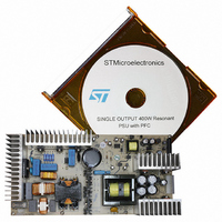
DEMO BOARD FOR L6599
Manufacturer
STMicroelectronics
Type
Power Factor Correctionr
Specifications of EVAL6599-400W-S
Main Purpose
AC/DC, Primary Side and PFC
Outputs And Type
3, Isolated
Power - Output
400W
Voltage - Output
200V, 5V, 3.3V
Current - Output
2A, 1A, 700mA
Voltage - Input
90 ~ 264VAC
Regulator Topology
Resonant
Board Type
Fully Populated
Utilized Ic / Part
L6563, L6599
Input Voltage
90 V to 264 V
Output Voltage
3.3 V to 200 V
Dimensions
132 mm x 265 mm
Product
Power Management Modules
Lead Free Status / RoHS Status
Lead free / RoHS Compliant
For Use With/related Products
L6599
Other names
497-5856
Available stocks
Company
Part Number
Manufacturer
Quantity
Price


AN2492
List of figures
Figure 1.
Figure 2.
Figure 3.
Figure 4.
Figure 5.
Figure 6.
Figure 7.
Figure 8.
Figure 9.
Figure 10.
Figure 11.
Figure 12.
Figure 13.
Figure 14.
Figure 15.
Figure 16.
Figure 17.
Figure 18.
Figure 19.
Figure 20.
Figure 21.
Figure 22.
Figure 23.
Figure 24.
Figure 25.
Figure 26.
Figure 27.
Figure 28.
Figure 29.
Figure 30.
Figure 31.
Figure 32.
Figure 33.
Figure 34.
PFC pre-regulator electrical diagram . . . . . . . . . . . . . . . . . . . . . . . . . . . . . . . . . . . . . . . . . . 6
Resonant converter electrical diagram . . . . . . . . . . . . . . . . . . . . . . . . . . . . . . . . . . . . . . . . . 7
Auxiliary converter electrical diagram . . . . . . . . . . . . . . . . . . . . . . . . . . . . . . . . . . . . . . . . . . 8
Compliance to EN61000-3-2 for harmonic reduction: full load . . . . . . . . . . . . . . . . . . . . . . . 9
Compliance to EN EN61000-3-2 for harmonic reduction: 70 W load . . . . . . . . . . . . . . . . . . 9
Compliance to JEIDA-MITI standard for harmonic reduction: full load . . . . . . . . . . . . . . . . . 9
Compliance to JEIDA-MITI standard for harmonic reduction: 70 W load . . . . . . . . . . . . . . . 9
Power factor vs. Vin & load. . . . . . . . . . . . . . . . . . . . . . . . . . . . . . . . . . . . . . . . . . . . . . . . . 10
Total harmonic distortion vs. Vin & load . . . . . . . . . . . . . . . . . . . . . . . . . . . . . . . . . . . . . . . 10
Overall efficiency versus output power at nominal mains voltages. . . . . . . . . . . . . . . . . . . 10
Overall efficiency versus input mains voltage at various output power levels . . . . . . . . . . 12
Resonant circuit primary side waveforms at full load . . . . . . . . . . . . . . . . . . . . . . . . . . . . . 13
Resonant circuit primary side waveforms at light load (about 30 W output power) . . . . . . 13
Resonant circuit primary side waveforms at no load condition . . . . . . . . . . . . . . . . . . . . . . 14
Resonant circuit secondary side waveforms: +200 V output . . . . . . . . . . . . . . . . . . . . . . . 14
Low frequency (100 Hz) ripple voltage on the +200 V output. . . . . . . . . . . . . . . . . . . . . . . 15
Load transition (0.4 A - 2 A) on +200 V output voltage. . . . . . . . . . . . . . . . . . . . . . . . . . . . 15
+200 V output short-circuit waveforms . . . . . . . . . . . . . . . . . . . . . . . . . . . . . . . . . . . . . . . . 17
Thermal map @115 V
Thermal map at 230 V
Peak measurement on LINE at 115 V
Peak measurement on NEUTRAL at 115 V
Peak measurement on LINE at 230 V
Peak measurement on NEUTRAL at 230 V
Electrical diagram . . . . . . . . . . . . . . . . . . . . . . . . . . . . . . . . . . . . . . . . . . . . . . . . . . . . . . . . 28
Pin side view . . . . . . . . . . . . . . . . . . . . . . . . . . . . . . . . . . . . . . . . . . . . . . . . . . . . . . . . . . . . 29
Electrical diagram . . . . . . . . . . . . . . . . . . . . . . . . . . . . . . . . . . . . . . . . . . . . . . . . . . . . . . . . 29
Mechanical aspect and pin numbering . . . . . . . . . . . . . . . . . . . . . . . . . . . . . . . . . . . . . . . . 30
Winding position on coil former. . . . . . . . . . . . . . . . . . . . . . . . . . . . . . . . . . . . . . . . . . . . . . 30
Electrical diagram . . . . . . . . . . . . . . . . . . . . . . . . . . . . . . . . . . . . . . . . . . . . . . . . . . . . . . . . 31
Auxiliary transformer winding position on coil former . . . . . . . . . . . . . . . . . . . . . . . . . . . . . 32
Copper tracks . . . . . . . . . . . . . . . . . . . . . . . . . . . . . . . . . . . . . . . . . . . . . . . . . . . . . . . . . . . 32
Thru-hole component placing and top silk screen . . . . . . . . . . . . . . . . . . . . . . . . . . . . . . . 33
SMT component placing and bottom silk screen . . . . . . . . . . . . . . . . . . . . . . . . . . . . . . . . 33
AC
AC
- full load . . . . . . . . . . . . . . . . . . . . . . . . . . . . . . . . . . . . . . . . . . . 19
- full load . . . . . . . . . . . . . . . . . . . . . . . . . . . . . . . . . . . . . . . . . . . 19
AC
AC
and full load . . . . . . . . . . . . . . . . . . . . . . . . . . . . 20
and full load . . . . . . . . . . . . . . . . . . . . . . . . . . . . 21
AC
AC
and full load . . . . . . . . . . . . . . . . . . . . . . . . 20
and full load . . . . . . . . . . . . . . . . . . . . . . . . 21
List of figures
3/35
Related parts for EVAL6599-400W-S
Image
Part Number
Description
Manufacturer
Datasheet
Request
R

Part Number:
Description:
EVAL BOARD FOR L6599
Manufacturer:
STMicroelectronics
Datasheet:

Part Number:
Description:
EVAL BOARD FOR L6599
Manufacturer:
STMicroelectronics
Datasheet:

Part Number:
Description:
DEMO BOARD FOR L6599
Manufacturer:
STMicroelectronics
Datasheet:

Part Number:
Description:
STMicroelectronics [RIPPLE-CARRY BINARY COUNTER/DIVIDERS]
Manufacturer:
STMicroelectronics
Datasheet:
Part Number:
Description:
STMicroelectronics [LIQUID-CRYSTAL DISPLAY DRIVERS]
Manufacturer:
STMicroelectronics
Datasheet:

Part Number:
Description:
BOARD EVAL FOR MEMS SENSORS
Manufacturer:
STMicroelectronics
Datasheet:
Part Number:
Description:
NPN TRANSISTOR POWER MODULE
Manufacturer:
STMicroelectronics
Datasheet:
Part Number:
Description:
TURBOSWITCH ULTRA-FAST HIGH VOLTAGE DIODE
Manufacturer:
STMicroelectronics
Datasheet:
Part Number:
Description:
Manufacturer:
STMicroelectronics
Datasheet:
Part Number:
Description:
DIODE / SCR MODULE
Manufacturer:
STMicroelectronics
Datasheet:
Part Number:
Description:
DIODE / SCR MODULE
Manufacturer:
STMicroelectronics
Datasheet:
Part Number:
Description:
Search -----> STE16N100
Manufacturer:
STMicroelectronics
Datasheet: