EVAL6599-400W-S STMicroelectronics, EVAL6599-400W-S Datasheet - Page 17
EVAL6599-400W-S
Manufacturer Part Number
EVAL6599-400W-S
Description
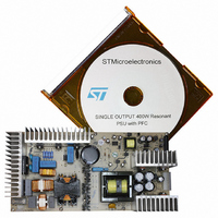
DEMO BOARD FOR L6599
Manufacturer
STMicroelectronics
Type
Power Factor Correctionr
Specifications of EVAL6599-400W-S
Main Purpose
AC/DC, Primary Side and PFC
Outputs And Type
3, Isolated
Power - Output
400W
Voltage - Output
200V, 5V, 3.3V
Current - Output
2A, 1A, 700mA
Voltage - Input
90 ~ 264VAC
Regulator Topology
Resonant
Board Type
Fully Populated
Utilized Ic / Part
L6563, L6599
Input Voltage
90 V to 264 V
Output Voltage
3.3 V to 200 V
Dimensions
132 mm x 265 mm
Product
Power Management Modules
Lead Free Status / RoHS Status
Lead free / RoHS Compliant
For Use With/related Products
L6599
Other names
497-5856
Available stocks
Company
Part Number
Manufacturer
Quantity
Price


AN2492
2.6
activated that shuts down the device and, in case of continuous overload/short circuit,
results in continuous intermittent operation with a user-defined duty cycle. This function is
accomplished by the DELAY pin 2 of the resonant controller, by means of the capacitor C24
and the parallel resistor R37 connected to ground. As the voltage on the ISEN pin exceeds
0.8V, the first OCP comparator, in addition to discharging CSS, turns on an internal current
generator that via the DELAY pin charges C24. As the voltage on C24 reaches 3.5 V, the
L6599 stops switching and the internal generator is turned off, so that C24 will now be slowly
discharged by R37. The IC will restart when the voltage on C24 becomes less than 0.3 V.
Additionally, if the voltage on the ISEN pin reaches 1.5 V for any reason (e.g. transformer
saturation), the second comparator will be triggered, the device will shut down and the
operation will be resumed after an on-off cycle.
protection sequence described above. The on-off operation is controlled by the voltage on
pin 2 (DELAY), providing for the hiccup mode of the circuit. Thanks to this control pin, the
designer can select the hiccup mode timing and thus keep the average output current at a
safe level.
Figure 18. +200 V output short-circuit waveforms
Overvoltage protection
Both the PFC pre-regulator and the resonant converter are equipped with their own
overvoltage protection circuit. The PFC controller is internally equipped with a dynamic and
a static overvoltage protection circuit sensing the current flowing through the error amplifier
compensation network and entering in the COMP pin (#2). When this current reaches about
18 µA, the output voltage of the multiplier is forced to decrease, thus reducing the energy
drawn from the mains. If the current exceeds 20 µA, the OVP is triggered (Dynamic OVP),
and the external power transistor is switched off until the current falls approximately below 5
µA. However, if the overvoltage persists (e.g. in case the load is completely disconnected),
the error amplifier will eventually saturate low, triggering an internal comparator (Static OVP)
that will keep the external power switch turned off until the output voltage comes back close
to the regulated value. Moreover, in the L6563 there is additional protection against loop
failures using an additional divider (R5, R7, R9, R16 and R25) connected to a dedicated pin
(PFC_OK, Pin 7) protecting the circuit in case of loop failures, disconnection, or deviation
from the nominal value of the feedback loop divider. Hence the PFC output voltage is always
Figure 18.
illustrates the short-circuit
Ch1: half-bridge voltage on pin
14
Ch2: + 200 V output current
Ch3: pin 6 (ISEN)
Ch4: pin 2 (DELAY)
Electrical test results
17/35
Related parts for EVAL6599-400W-S
Image
Part Number
Description
Manufacturer
Datasheet
Request
R

Part Number:
Description:
EVAL BOARD FOR L6599
Manufacturer:
STMicroelectronics
Datasheet:

Part Number:
Description:
EVAL BOARD FOR L6599
Manufacturer:
STMicroelectronics
Datasheet:

Part Number:
Description:
DEMO BOARD FOR L6599
Manufacturer:
STMicroelectronics
Datasheet:

Part Number:
Description:
STMicroelectronics [RIPPLE-CARRY BINARY COUNTER/DIVIDERS]
Manufacturer:
STMicroelectronics
Datasheet:
Part Number:
Description:
STMicroelectronics [LIQUID-CRYSTAL DISPLAY DRIVERS]
Manufacturer:
STMicroelectronics
Datasheet:

Part Number:
Description:
BOARD EVAL FOR MEMS SENSORS
Manufacturer:
STMicroelectronics
Datasheet:
Part Number:
Description:
NPN TRANSISTOR POWER MODULE
Manufacturer:
STMicroelectronics
Datasheet:
Part Number:
Description:
TURBOSWITCH ULTRA-FAST HIGH VOLTAGE DIODE
Manufacturer:
STMicroelectronics
Datasheet:
Part Number:
Description:
Manufacturer:
STMicroelectronics
Datasheet:
Part Number:
Description:
DIODE / SCR MODULE
Manufacturer:
STMicroelectronics
Datasheet:
Part Number:
Description:
DIODE / SCR MODULE
Manufacturer:
STMicroelectronics
Datasheet:
Part Number:
Description:
Search -----> STE16N100
Manufacturer:
STMicroelectronics
Datasheet: