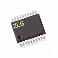
ZGP32302010ZDH Zilog, ZGP32302010ZDH Datasheet - Page 23

ZGP32302010ZDH
Manufacturer Part Number
ZGP32302010ZDH
Description
ADAPTER ICE Z8 GP ZGP323 20SSOP
Manufacturer
Zilog
Datasheet
1.ZGP32302010ZDH.pdf
(25 pages)
Specifications of ZGP32302010ZDH
Convert From (adapter End)
20-Pin DIP
Convert To (adapter End)
20-Pin SSOP
For Use With/related Products
Z8 GP ZGP323
Lead Free Status / RoHS Status
Contains lead / RoHS non-compliant
Other names
269-3738
Connector J8 on the emulator front panel (see Figures 4 and 5) provides a ground connec-
tion on all three pins.
Connector J9 on the emulator front panel (see Figures 4 and 5) provides access to the fol-
lowing functions:
•
•
Using J9 Pin 3, External Trigger Out
The Z8 GP ICE external trigger out feature is always enabled. Set your trace and event
system parameters, then run your code. When the event you set up occurs, pin 3 of con-
nector J9 goes HIGH and stays HIGH as long as the event is active. The bigger the event
window, the longer trigger out stays HIGH.
How to Set Connector J9 Pin 1, External Trigger In (see Figure 5 on page 6)
To use the Z8 GP ICE external trigger in feature:
1. With the ledblink_c.pro project open in ZDS II as described in “Running a Sample
2. In the
3. Select either 0 or 1 to trigger on trigger low or high, respectively (edge-triggering not
4. Click the OK button to set the trace and event system parameters. If you set trigger=1
Adapter Kit Ordering Information
The adapter kits described in Table 4 contain the target PODs, program adapters, and
package converters needed for all ZGP323 components. Use the information provided in
Table 4 to order the appropriate adapter kit for your development needs.
Ironwood adapters can be ordered at http://www.ironwoodelectronics.com/.
UM019302-0407
Pin 3 provides a HIGH external trigger out for use in triggering a device such as a
logic analyzer or oscilloscope. Pin 3 is under software control, and can be set to acti-
vate through the ZDS II trace and event system. The trigger can be set to toggle or
pulse.
Pin 1 provides an input for an external HIGH or LOW trigger in, allowing use of an
external trigger as an event for the ZDS II trace and event system.
Project” on page 14, select
check the
supported).
in the
ates an event in the ZDS II trace and event system. If you set trigger=0, then a LOW
on pin 1 of connector J9 generates an event.
Trace and Event System
Trace and Event System
Trigger In
Z8 GP™ ZGP323 In-Circuit Emulator and Development Platform
box.
Tools > Trace and Event System
window, then a HIGH on pin 1 of connector J9 gener-
window, select an Event entry. In the When section,
Adapter Kit Ordering Information
.
User Manual
Page 23


