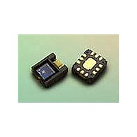
HDJD-JD07 Avago Technologies US Inc., HDJD-JD07 Datasheet - Page 13

HDJD-JD07
Manufacturer Part Number
HDJD-JD07
Description
KIT DEV RGB DCS 2.2X2.2
Manufacturer
Avago Technologies US Inc.
Datasheet
1.HDJD-JD07.pdf
(19 pages)
Specifications of HDJD-JD07
Sensor Type
Light, Color Sensor
Interface
USB
Voltage - Supply
2.5V
Utilized Ic / Part
*
Lead Free Status / RoHS Status
Lead free / RoHS Compliant
PC Software Guide
Avago’s HDJD-JD07 Digital Color Sensor Development
Kit software is developed to be a tool for user to acquire
knowledge on how to use ADJD-S311-CR999 and how
color sensor can be applied. The interactive graphical
user interface has made the software to be user friendly
and easy to use. The same software can be used for both
reflective and transmissive mode.
Software Installation
To install the software to the PC:
1. Insert the installation CD to the CD-ROM drive
2. Click Start, then click Run
3. Type D:\setup and press Enter.
IMPORTANT: Use the appropriate drive letter in the above
command to install the software. CD-ROMs are commonly
“D:”.
The installation program will guide you through the
software installation.
Note: If any text box appeared noting that the current
system file has a newer version, just select ‘Ignore’ button.
Software GUI Guide
11
1. Configuration and control registers
2. Sensor setup registers
3. Sensor and offset registers
5. Color Conversion
6. Comms
Software Features:
•
•
•
•
•
•
•
•
•
•
4. Console
These are the internal registers that configure the color
sensor and control its functions.
These boxes contain the sensor gain settings that
adjust the sensitivity of the sensor. The user can key in
data into these boxes to manually change the gain or
can use the white calibration feature to generate the
optimum gain value.
The sensor registers store the digitized readings of
the color sensor and the offset register store the offset
value of the color sensor.
The console is a general-purpose method to write
to and read from the sensor. The user enters just the
register address to read. To write, enter both the
address and data.
Display the sensor readings in XYZ tristimulus values,
CIE Yxy color space and L*a*b* Color space. The XYZ,
Yxy and Lab value will only be shown if the checkbox
for “Activate Color Chart/Conversion” is checked after
some settings are made.
The user needs to check the communication between
the software and the board before using the software
by pressing the “test” button. Red means the
communications test failed. Green means it passed.
Compatible with Windows XP and 2000.
Developed with Visual Basic.
List of color sensor registers for user references.
Display of R, G, B and C readings.
Manual gain selection.
White calibration (Auto-gain feature).
Color Conversion to standard color space.
Data-log features to save the R,G,B and C readings to
text and excel files.
CIE xy chart to display the color measured.
PWM Window to turn on/off and control the bright-
ness of white LED.


