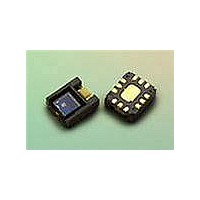
HDJD-JD07 Avago Technologies US Inc., HDJD-JD07 Datasheet - Page 11

HDJD-JD07
Manufacturer Part Number
HDJD-JD07
Description
KIT DEV RGB DCS 2.2X2.2
Manufacturer
Avago Technologies US Inc.
Datasheet
1.HDJD-JD07.pdf
(19 pages)
Specifications of HDJD-JD07
Sensor Type
Light, Color Sensor
Interface
USB
Voltage - Supply
2.5V
Utilized Ic / Part
*
Lead Free Status / RoHS Status
Lead free / RoHS Compliant
Other functions:
1. Selecting internal or external power supply for the
2. Selecting White LED control
color sensor.
Use J1 to select the source 2.6V for the color sensor. If
external 2.6V is chosen, connect the supply to TB1. The
external supply is to ease the measurement of sensor’s
power consumption.
The white LED can be turn on/off using 3 methods
which is PWM from microcontroller, Sleep pin of color
sensor during external clock mode and Jumper J6.
Use jumper J7 to select either use PWM or Sleep pin,
leaving the J6 disconnected. Connecting J6 will turn
on the White LED using constant current bypassing
the PWM and Sleep selection.
The LED can be dim by changing the current by
adjusting the variable resistor VR2. The LED current
can be measured by measuring the voltage across
R20 using test pin TP1/TP2. The current can then be
calculated with I = V/10. (Note: The max current for the
white LED is recommended at 10mA). Another way
to change the brightness of the LED is by changing
the PWM duty cycle from the software GUI although
100% duty cycle/constant current is recommended for
sensor operation.
3. Sleep function
4. Color Sensor reset
5. External clock
Connect jumper J4 to put the sensor into sleep mode to
minimize power consumption when sensor not in use.
Push SW2 to reset the color sensor.
The sensor is operating with internal clock at typical
frequency of 26MHz. To use external clock connect the
clock signal to pin 1 of J9 (the pin located closer to J8)
while pin 2 of J9 is the reference ground.


