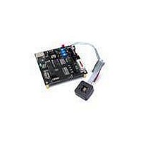
HDJD-JD06 Avago Technologies US Inc., HDJD-JD06 Datasheet - Page 6

HDJD-JD06
Manufacturer Part Number
HDJD-JD06
Description
KIT DEV RGB COLOR SENSOR 16-QFN
Manufacturer
Avago Technologies US Inc.
Specifications of HDJD-JD06
Sensor Type
Light, Color Sensor
Sensing Range
RGB
Interface
Analog
Voltage - Supply
4.5 V ~ 5.5 V
Embedded
No
Utilized Ic / Part
ADJD-E622-QR999
For Use With/related Products
ADJD-E622-QR999
Lead Free Status / RoHS Status
Not applicable / Not applicable
4.0 Hardware Setup & Configuration
Setup:
This HDJD-JD06 has designed with 2 different selec-
tions to obtain +5VDC. User may either select USB Port
or Adapter Port as its +5VDC supply with respect to the
changes of the “Jumper”.
Connect the USB cable from the computer to the control-
ler board.
Select the jumper to the power source to use. If power
from adapter is chosen, connect the adapter to the
adapter socket.
Precaution: Please make sure that the adapter voltage is
between 9V to 20V.
Figure 4.0: Selecting the power supply
Connect the sensor module to the controller board. Make
sure the orientation is correct by checking the pin 10 that
is without cable is connected to NC.
Figure 4.1: The right orientation to connect the sensor module to controller board
The side without
cable is connected
to NC
Jumper for power
source selection
adapter
socket
Power
Figure 4.2: Controller board with all interface connected
To power on:
Turn on the power switch (SW1). The red LED will light up
to indicate there is power supply to the board.
The green LED will light up if the USB cable is connected
indicating there are communication between the con-
troller board and the computer.
Figure 4.3
Power
switch
SW1:
OFF
ON


