EVAL-ADT7470EB Analog Devices Inc, EVAL-ADT7470EB Datasheet - Page 33
EVAL-ADT7470EB
Manufacturer Part Number
EVAL-ADT7470EB
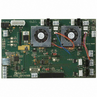
Description
BOARD EVALUATION FOR ADT7470
Manufacturer
Analog Devices Inc
Datasheet
1.ADT7470ARQZ.pdf
(40 pages)
Specifications of EVAL-ADT7470EB
Sensor Type
Temperature
Interface
SMBus (2-Wire/I²C)
Voltage - Supply
3 V ~ 5.5 V
Embedded
No
Utilized Ic / Part
ADT7470
Lead Free Status / RoHS Status
Contains lead / RoHS non-compliant


Table 36. Register 0x58 to Register 0x67. Fan Tachometer Limit Registers.
Register Address
0x58
0x59
0x5A
0x5B
0x5C
0x5D
0x5E
0x5F
0x60
0x61
0x62
0x63
0x64
0x65
0x66
0x67
Exceeding any of the tach min limit registers shown in Table 36 by 1 indicates that the fan is running too slowly or has stalled.
The appropriate status bit is set in Interrupt Status Register 2 to indicate the fan failure.
Exceeding any of the tach max limit registers by 1 indicates that the fan is too fast. The appropriate status bit is set in Interrupt Status
Register 2 to indicate the fan failure.
Table 37. Register 0x68. PWM1/PWM2 Configuration Register (Power-On Default = 0x00).
Bit Name
[0]
[1]
[2]
[3]
[4] INV2
[5] INV1
[6] BHVR2
[7] BHVR1
Read/Write
Read/Write
Read/Write
Read/Write
Read/Write
Read/Write
Read/Write
Read/Write
Read/Write
Read/Write
Read/Write
Read/Write
Read/Write
Read/Write
Read/Write
Read/Write
Read/Write
Read/Write
N/A
N/A
N/A
N/A
Read/Write
Read/Write
Read/Write
Read/Write
Description
Tach 1 min low byte
Tach 1 min high byte
Tach 2 min low byte
Tach 2 min high byte
Tach 3 min low byte
Tach 3 min high byte
Tach 4 min low byte
Tach 4 min high byte
Tach 1 max low byte
Tach 1 max high byte
Tach 2 max low byte
Tach 2 max high byte
Tach 3 max low byte
Tach 3 max high byte
Tach 4 max low byte
Tach 4 max high byte
Description
Set to 0 (default).
Set to 0 (default).
Set to 0 (default).
Set to 0 (default).
Setting this bit to 1 inverts the PWM2 output. Default = 0.
Setting this bit to 1 inverts the PWM1 output. Default = 0.
This bit assigns fan behavior for PWM2 output.
0 = manual fan control mode (PWM duty cycle controlled in software).
1 = automatic fan control mode
This bit assigns fan behavior for PWM1 output.
0 = manual fan control mode (PWM duty cycle controlled in software).
1 = automatic fan control mode.
Rev. C | Page 33 of 40
Power-On Default
0xFF
0xFF
0xFF
0xFF
0xFF
0xFF
0xFF
0xFF
0x00
0x00
0x00
0x00
0x00
0x00
0x00
0x00
ADT7470
Related parts for EVAL-ADT7470EB
Image
Part Number
Description
Manufacturer
Datasheet
Request
R


Part Number:
Description:
BOARD EVAL FOR SI270X-A
Manufacturer:
Silicon Laboratories Inc
Datasheet:

Part Number:
Description:
BUCK CONV REF DESIGN KIT IP1201
Manufacturer:
International Rectifier
Datasheet:
Part Number:
Description:
BOARD DEMO SYNC DUAL BUCK CNVTER
Manufacturer:
International Rectifier
Datasheet:
Part Number:
Description:
BOARD DEMO SYNC BUCK CONVETER
Manufacturer:
International Rectifier
Datasheet:

Part Number:
Description:
EVALBOARD/EB Omnidirectional microphone - Analog
Manufacturer:
Analog Devices
Datasheet:
Part Number:
Description:
EVALBOARD/EB Omnidirectional microphone - Analog
Manufacturer:
Analog Devices
Datasheet:


Part Number:
Description:
BOARD EVAL LED DRIVER LT3756
Manufacturer:
Linear Technology
Datasheet:

Part Number:
Description:
BOARD EVAL FOR AD7741/7742
Manufacturer:
Analog Devices Inc
Datasheet:

Part Number:
Description:
±1.7g Dual-Axis IMEMS Accelerometer Evaluation Board
Manufacturer:
Analog Devices Inc
Datasheet:

Part Number:
Description:
IC MULTIPLIER ANALOG 8-SOIC T/R
Manufacturer:
Analog Devices Inc
Datasheet:

Part Number:
Description:
IC ANALOG MULTIPLIER 8-DIP
Manufacturer:
Analog Devices Inc
Datasheet:
Part Number:
Description:
IC ANALOG MULTIPLIER 8-SOIC
Manufacturer:
Analog Devices Inc
Datasheet:
Part Number:
Description:
IC ANALOG MULTIPLIER 8-DIP
Manufacturer:
Analog Devices Inc
Datasheet: