EVAL-ADT7470EB Analog Devices Inc, EVAL-ADT7470EB Datasheet - Page 26
EVAL-ADT7470EB
Manufacturer Part Number
EVAL-ADT7470EB
Description
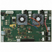
BOARD EVALUATION FOR ADT7470
Manufacturer
Analog Devices Inc
Datasheet
1.ADT7470ARQZ.pdf
(40 pages)
Specifications of EVAL-ADT7470EB
Sensor Type
Temperature
Interface
SMBus (2-Wire/I²C)
Voltage - Supply
3 V ~ 5.5 V
Embedded
No
Utilized Ic / Part
ADT7470
Lead Free Status / RoHS Status
Contains lead / RoHS non-compliant


ADT7470
AUTOMATIC FAN SPEED CONTROL
In automatic fan speed control mode, fan speed automatically
varies with temperature and without CPU intervention, once
initial parameters are set up. The advantage is that when a
system hangs, the user is guaranteed that the system is protected
from overheating.
Automatic fan speed control mode is recommended for use
only when temperatures > 8°C. In automatic fan control mode,
if the temperature drops below 0°C, the fans automatically
turn on.
For each thermal zone, when the temperature exceeds T
the fans turn on at PWM
reaches T
To configure each fan into automatic fan control mode, the
BHVR bit for that fan must be set to 1. See Table 22 for more
details.
To control the fans in automatic fan control mode, a number of
parameters for each fan should be set up. The PWM minimum
and maximum duty cycles, as well as the minimum temperature
at which each fan turns on, should be configured. Which
TMP05 controls which fan also needs to be configured.
What follows are the automatic fan control configuration steps:
1.
2.
3.
4.
5.
6.
Put the fans into automatic fan control mode, by setting
the BHVR bits for each fan to 1.
Determine which TMP05 is to control the fan, by
configuring Registers 0x7C and 0x7D. Any TMP05, can
control any fan, or the hottest TMP05 can control the fan.
Set the minimum temperature for each fan, by writing to
Registers 0x6E to 0x70. When the temperature exceeds
T
Set PWM
Registers 0x6A to 0x6D.
Set PWM
to registers 0x38 to 0x3B.
Write to the STRT bit in Configuration Register 1 (0x40
Bit[0]) to start the ADT7470 monitoring cycle. Set Bit 7 in
this register to 1 to enable the TMP05 start pulse.
MIN
, the fan runs at PWM
MIN
+ 20°C, the fans increase in speed to PWM
MIN
MAX
, the minimum PWM duty cycle, by writing to
, the maximum PWM duty cycle, by writing
MIN
duty cycle. When the temperature
MIN
.
MAX
MIN
,
.
Rev. C | Page 26 of 40
PWM Min Duty Cycle
The PWM min duty cycle registers, at address 0x6A to 0x6D,
set the PWM duty cycle at which the fans turn on in automatic
fan control mode.
The value to be programmed into the PWM Min Duty Cycle
registers can be calculated as follows:
Example: For a PWM Min Duty Cycle of 30%
The PWM min duty cycle registers have a default value of
0x80, which corresponds to a duty cycle of 50% on the PWM
output pin.
PWN Max Duty Cycle
For each fan, the maximum PWM duty cycle can be set by
writing to Registers 0x38 to 0x3B.
The value to be programmed into the PWM max duty cycle
registers can be calculated as follows:
Example: For a PWM Max Duty Cycle of 90%
The PWM max duty cycle registers have a default value of 0xFF,
which corresponds to a Logic 1 on the PWM output pin.
PWM Current Duty Cycle
In automatic fan control mode, the current PWM duty cycle for
each fan is recorded in the PWM current duty cycle registers,
(0x02 to 0x35). By reading these registers, the user can keep
track of the current duty cycle on each PWM output. During
fan start up, these registers report back 0x00.
If the FULLSPEED pin is activated, to blast the fans to the
maximum possible PWM ( logic high), the PWM current duty
cycle register is not updated.
Value (decimal) = Desired PWM duty cycle/0.39
Value (decimal) = 30/0.39 = 77 decimal
Value = 77 decimal or 4D hex
Value (decimal) = Desired PWM duty cycle/0.39
Value (decimal) = 90/0.39 = 230 decimal
Value = 230 decimal or E6 hex
Related parts for EVAL-ADT7470EB
Image
Part Number
Description
Manufacturer
Datasheet
Request
R


Part Number:
Description:
BOARD EVAL FOR SI270X-A
Manufacturer:
Silicon Laboratories Inc
Datasheet:

Part Number:
Description:
BUCK CONV REF DESIGN KIT IP1201
Manufacturer:
International Rectifier
Datasheet:
Part Number:
Description:
BOARD DEMO SYNC DUAL BUCK CNVTER
Manufacturer:
International Rectifier
Datasheet:
Part Number:
Description:
BOARD DEMO SYNC BUCK CONVETER
Manufacturer:
International Rectifier
Datasheet:

Part Number:
Description:
EVALBOARD/EB Omnidirectional microphone - Analog
Manufacturer:
Analog Devices
Datasheet:
Part Number:
Description:
EVALBOARD/EB Omnidirectional microphone - Analog
Manufacturer:
Analog Devices
Datasheet:


Part Number:
Description:
BOARD EVAL LED DRIVER LT3756
Manufacturer:
Linear Technology
Datasheet:

Part Number:
Description:
BOARD EVAL FOR AD7741/7742
Manufacturer:
Analog Devices Inc
Datasheet:

Part Number:
Description:
±1.7g Dual-Axis IMEMS Accelerometer Evaluation Board
Manufacturer:
Analog Devices Inc
Datasheet:

Part Number:
Description:
IC MULTIPLIER ANALOG 8-SOIC T/R
Manufacturer:
Analog Devices Inc
Datasheet:

Part Number:
Description:
IC ANALOG MULTIPLIER 8-DIP
Manufacturer:
Analog Devices Inc
Datasheet:
Part Number:
Description:
IC ANALOG MULTIPLIER 8-SOIC
Manufacturer:
Analog Devices Inc
Datasheet:
Part Number:
Description:
IC ANALOG MULTIPLIER 8-DIP
Manufacturer:
Analog Devices Inc
Datasheet: