EVAL-AD5392EB Analog Devices Inc, EVAL-AD5392EB Datasheet - Page 6
EVAL-AD5392EB
Manufacturer Part Number
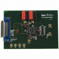
EVAL-AD5392EB
Description
BOARD EVAL FOR AD5392
Manufacturer
Analog Devices Inc
Datasheet
1.EVAL-AD5390EBZ.pdf
(12 pages)
Specifications of EVAL-AD5392EB
Number Of Dac's
16
Number Of Bits
14
Outputs And Type
16, Single Ended
Sampling Rate (per Second)
125k
Data Interface
Serial
Settling Time
8µs
Dac Type
Voltage
Voltage Supply Source
Single
Operating Temperature
-40°C ~ 85°C
Utilized Ic / Part
AD5392
Lead Free Status / RoHS Status
Contains lead / RoHS non-compliant


EVAL-AD5390/91/92EB
PROGRAM OUTPUT RANGE
You can reduce the output range of each DAC channel using the
offset and gain registers. To access the Output Range dialog
box, select Program Output Range from the Dac menu.
1.
2.
SPECIAL FUNCTION REGISTER
The Special Function Register dialog box allows access to all
the register functions. To access this dialog box, select Special
Function Register from the Register menu.
Software Clear
The Software Clear area allows you to clear the DAC channels
to a user-specified value:
1.
2.
Type the desired full-scale and zero-scale values in the
appropriate boxes.
Click Program Range. The m and c registers are
programmed with the displayed values, and the output
range is set to the user-selected values.
If you want to clear the DAC channels to the user-specified
value (default value is 0 V), click Soft Clear.
If you want to program the user-specified value, type the
value in the Enter Code box and click Write Code.
Figure 6.
Rev. 0 | Page 6 of 12
Figure 8.
Monitor Channel
The Monitor Channel area allows you to monitor the DAC
channels via the MON_OUT pin. Before the monitor function
can operate, you must enable it in the control register:
1.
2.
3.
4.
5.
Power Up/Down and Software Reset Functions
Click Power Down, Power Up, or Reset, as needed, to activate
or deactivate these functions.
CONTROL REGISTER
To access the Control Register dialog box, select Register from
the AD5390/91/92 Evaluation Software dialog box. The
Control Register dialog box allows user access to all the control
register functions. The current bit values of the control register
are displayed in the Contents of Control Register area. Eight
functions are available, as shown in Figure 8.
Type the AV
value is used as the reference for the on-board ADC.
Select the channel that you want to monitor in the Select
Channel to Monitor box.
Optional: To three-state the MON_OUT pin, select the
Tri-State check box.
Click Program.
To measure and display the voltage at the MON_OUT pin,
click Measure Voltage.
CC
value in the Enter AV
Figure 7.
CC
Value box. This
Related parts for EVAL-AD5392EB
Image
Part Number
Description
Manufacturer
Datasheet
Request
R

Part Number:
Description:
ENERCHIP CC EVAL KIT
Manufacturer:
Cymbet Corporation
Datasheet:

Part Number:
Description:
BOARD EVAL FOR AD976
Manufacturer:
Analog Devices Inc
Datasheet:

Part Number:
Description:
BOARD EVAL FOR ADXL345
Manufacturer:
Analog Devices Inc
Datasheet:

Part Number:
Description:
ENERCHIP CC SEH EVAL KIT
Manufacturer:
Cymbet Corporation
Datasheet:

Part Number:
Description:
ENERCHIP EP ENERGY HARVEST EVAL
Manufacturer:
Cymbet Corporation
Datasheet:

Part Number:
Description:
EVAL BOARD FOR TW6864-LB2-GR
Manufacturer:
Intersil
Datasheet:
Part Number:
Description:
EVAL BOARD FOR TW8816-LB3-GR
Manufacturer:
Intersil
Datasheet:
Part Number:
Description:
EVAL BOARD FOR TW8817-TA3-GRS
Manufacturer:
Intersil
Datasheet:

Part Number:
Description:
EVALUATION MODULE FOR ADUM4160
Manufacturer:
Analog Devices Inc
Datasheet:

Part Number:
Description:
BOARD EVALUATION ADCMP581BCP
Manufacturer:
Analog Devices Inc
Datasheet:
Part Number:
Description:
BOARD EVALUATION ADM1041
Manufacturer:
Analog Devices Inc
Datasheet:

Part Number:
Description:
EVAL BOARD FOR STM32F107VCT
Manufacturer:
STMicroelectronics
Datasheet:
Part Number:
Description:
BOARD EVAL FOR AD1954
Manufacturer:
Analog Devices Inc
Datasheet:
Part Number:
Description:
BOARD EVAL FOR AD1955
Manufacturer:
Analog Devices Inc
Datasheet:

Part Number:
Description:
BOARD EVAL FOR AD7655
Manufacturer:
Analog Devices Inc
Datasheet: