EVAL-AD5392EB Analog Devices Inc, EVAL-AD5392EB Datasheet
EVAL-AD5392EB
Specifications of EVAL-AD5392EB


Related parts for EVAL-AD5392EB


EVAL-AD5392EB Summary of contents
Page 1
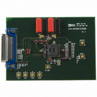
... Direct hook-up to printer port software for control of DACs Socketed AD539x for easy replacement INTRODUCTION This evaluation board is for the AD5390/AD5391/AD5392, 8-/16-channel, 12-/14-bit DACs. The AD539x parts contain 8/16, 12-/14-bit DACs in one package. They have a maximum output voltage span derived from a reference voltage of 2 ...
Page 2
... EVAL-AD5390/91/92EB TABLE OF CONTENTS Link and Switch Options ................................................................. 3 Link and Switch Option Setup for PC Control ........................ 4 Evaluation Board Software .............................................................. 5 Software Installation .................................................................... 5 Load DAC Channels .................................................................... 5 Channel Calibration..................................................................... 5 Program Output Range ............................................................... 6 REVISION HISTORY 7/04—Revision 0: Initial Version Special Function Register.............................................................6 Control Register ............................................................................6 Component Listing ...........................................................................7 ESD Caution...................................................................................7 Evaluation Board Schematics ...
Page 3
... LINK AND SWITCH OPTIONS The link and switch options on the evaluation board should be set for the required operating setup before using the board. The functions of the link and switch options are described in Table 1. Table 1. Link Options Link/Switch No. Function LK1 For normal operation, this link should not be inserted. ...
Page 4
... EVAL-AD5390/91/92EB LINK AND SWITCH OPTION SETUP FOR PC CONTROL The PC controls the AD539x over the SPI interface, which must be enabled for PC control. The link and switch options for PC control are listed in Table 2. Table 2. Link and Switch Options for PC Control Link/Switch No. State Function ...
Page 5
... The EVAL-AD5390/91/92EB evaluation kit includes self- installing software on CD-ROM. If the setup file does not run automatically, you can run setup.exe from the CD-ROM. The evaluation board software is compatible with Windows® Windows XP. Ensure that the Centronics cable connects the PC to the EVAL-AD5390/91/92EB evaluation board. ...
Page 6
... CONTROL REGISTER To access the Control Register dialog box, select Register from the AD5390/91/92 Evaluation Software dialog box. The Control Register dialog box allows user access to all the control register functions. The current bit values of the control register are displayed in the Contents of Control Register area. Eight functions are available, as shown in Figure 8 ...
Page 7
... Header 20 Gold 50 Ω SMB Jack Header 07 Black Banana Socket Red Banana Socket Header (2 × 1 pin) Header (3 × 1 pin) Header (3 × 1 pin) Rev Page EVAL-AD5390/91/92EB Supplier/Number Analog Devices Plastronics 64QN50T19090-J Analog Devices Analog Devices FEC 911-975 FEC 499-675 FEC 197-130 FEC 498-580 ...
Page 8
... EVAL-AD5390/91/92EB EVALUATION BOARD SCHEMATICS Figure 9. Rev Page ...
Page 9
... Figure 10. Figure 11. Rev Page EVAL-AD5390/91/92EB ...
Page 10
... EVAL-AD5390/91/92EB Figure 12. Figure 13. Rev Page ...
Page 11
... Figure 14. Rev Page EVAL-AD5390/91/92EB ...
Page 12
... EVAL-AD5390EB EVAL-AD5391EB EVAL-AD5392EB Purchase of licensed I²C components of Analog Devices or one of its sublicensed Associated Companies conveys a license for the purchaser under the Philips I²C Patent Rights to use these components in an I²C system, provided that the system conforms to the I²C Standard Specification as defined by Philips. ...