PMF18WE1 Microchip Technology, PMF18WE1 Datasheet - Page 60
PMF18WE1
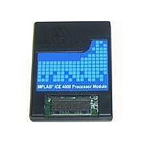
Manufacturer Part Number
PMF18WE1
Description
PROCESSOR MODULE FOR ICE4000
Manufacturer
Microchip Technology
Datasheet
1.ICE4000.pdf
(98 pages)
Specifications of PMF18WE1
Module/board Type
Processor Module
Product
Microcontroller Modules
Core Processor
PIC18F6585/6680/8585/8680
Lead Free Status / RoHS Status
Contains lead / RoHS non-compliant
For Use With/related Products
ICE4000
Lead Free Status / RoHS Status
Lead free / RoHS Compliant, Contains lead / RoHS non-compliant


MPLAB
DS51490A-page 54
ICE 4000 User’s Guide
7.4.1
This trace buffer can be viewed by selecting View>ICE Trace.
FIGURE 7-3:
MPLAB ICE 4000 offers a trace memory window that monitors much of the processor
operation. Up to 64K-1 (65535) instruction cycles can be displayed. The trace memory
window contains the following information for each execution cycle:
• Line – Cycle’s position relative to the trigger or halting point.
• Address (Addr) – Address of the instruction being fetched from program memory.
• Opcode (Op) – Instruction being fetched.
• Label (Label) – Label (if any) associated with the program memory address.
• Instruction – Disassembled instruction.
• Source Data Address (SA) – Address or symbol of the source data, if applicable.
• Source Data Value (SD) – Value of the source data, if applicable.
• Destination Data Address (DA) – Address or symbol of the destination data, if
• Destination Data Value (DD) – Value of the destination data, if applicable.
• Cycles – Time stamp value.
• Probe n – Value of the external input from logic probe n, for n = 0 through 7.
The approximate trigger cycle will be highlighted and will be numbered as line 0. All
other lines will be numbered based on this cycle. Cycles that occurred before the trig-
ger point will have a negative line number and cycles that occurred after the trigger
point will have a positive line number. If the trace buffer was displayed after a user halt,
a software breakpoint, or a complex trigger that halted the processor, the trigger point
will be the last traced cycle. If a complex trigger filled the trace buffer without halting the
processor, the trigger point will show the approximate cycle when the complex trigger
fired.
applicable.
Note: Due to the timing of processor signals, the data information will be skewed
The Trace Memory Window
by one cycle. Destination data values are actually skewed by two cycles,
but for display purposes, the trace buffer display compensates for one of
the delayed cycles.
TRACE MEMORY WINDOW – MPLAB ICE 4000, PIC18F452
2004 Microchip Technology Inc.
Related parts for PMF18WE1
Image
Part Number
Description
Manufacturer
Datasheet
Request
R

Part Number:
Description:
Manufacturer:
Microchip Technology Inc.
Datasheet:
Part Number:
Description:
Manufacturer:
Microchip Technology Inc.
Datasheet:
Part Number:
Description:
Manufacturer:
Microchip Technology Inc.
Datasheet:
Part Number:
Description:
Manufacturer:
Microchip Technology Inc.
Datasheet:
Part Number:
Description:
Manufacturer:
Microchip Technology Inc.
Datasheet:
Part Number:
Description:
Manufacturer:
Microchip Technology Inc.
Datasheet:
Part Number:
Description:
Manufacturer:
Microchip Technology Inc.
Datasheet:
Part Number:
Description:
Manufacturer:
Microchip Technology Inc.
Datasheet: