PMF18WE1 Microchip Technology, PMF18WE1 Datasheet - Page 21
PMF18WE1
Manufacturer Part Number
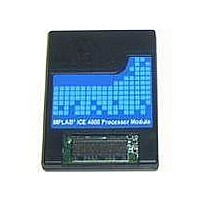
PMF18WE1
Description
PROCESSOR MODULE FOR ICE4000
Manufacturer
Microchip Technology
Datasheet
1.ICE4000.pdf
(98 pages)
Specifications of PMF18WE1
Module/board Type
Processor Module
Product
Microcontroller Modules
Core Processor
PIC18F6585/6680/8585/8680
Lead Free Status / RoHS Status
Contains lead / RoHS non-compliant
For Use With/related Products
ICE4000
Lead Free Status / RoHS Status
Lead free / RoHS Compliant, Contains lead / RoHS non-compliant


3.1
3.2
3.3
2004 Microchip Technology Inc.
INTRODUCTION
HIGHLIGHTS
CHECKING CONFIGURATION BIT VALUES
After installing MPLAB ICE 4000 and starting up the MPLAB IDE, MPLAB IDE must be
set up to correctly emulate the selected processor.
The steps needed to get started with MPLAB ICE 4000 are:
• Checking Configuration Bit Values
• Configuring the Communications Port
• Selecting Processor Power
• Setting Up the Processor Clock
• Setting Up Miscellaneous Hardware
• Using MPLAB IDE Projects and Work spaces
To view the values of configuration bits for your selected device, open the Configuration
Bits window by selecting Configure>Configuration Bits.
When you first select a device and start a project, default data sheet values for
configuration bits are used. These may not be what you want for development, e.g., you
may not want the watchdog timer enabled.
3.3.1
Determine whether or not the Watchdog Timer (WDT) will be needed. During
development, WDT is usually disabled. However, if a specific development requires the
WDT to be enabled, remember to set its prescaler.
3.3.2
If a processor has a mode that supports external program memory (Microprocessor or
Extended Microcontroller), select the mode here. Additional memory features are set
up on the Memory tab of the Settings dialog.
PIC18C601/801 devices use external memory exclusively (they have no on-chip
program memory), so there is no need for Processor mode selection bits. However, you
may use the Memory tab to set up whether the external memory is provided by the
emulator or the target.
3.3.3
Select the oscillator you will use for development here and the frequency for the
oscillator in Debugger>Settings, Clock tab (Section 3.6 “Setting Up the Processor
Clock”). Make sure you only enter frequencies that are available for the selected
oscillator.
Chapter 3. General Set Up
Watchdog Timer On/Off
Processor Mode and External Memory
Oscillator Settings
MPLAB
USER’S GUIDE
®
ICE 4000
DS51490A-page 15
Related parts for PMF18WE1
Image
Part Number
Description
Manufacturer
Datasheet
Request
R

Part Number:
Description:
Manufacturer:
Microchip Technology Inc.
Datasheet:
Part Number:
Description:
Manufacturer:
Microchip Technology Inc.
Datasheet:
Part Number:
Description:
Manufacturer:
Microchip Technology Inc.
Datasheet:
Part Number:
Description:
Manufacturer:
Microchip Technology Inc.
Datasheet:
Part Number:
Description:
Manufacturer:
Microchip Technology Inc.
Datasheet:
Part Number:
Description:
Manufacturer:
Microchip Technology Inc.
Datasheet:
Part Number:
Description:
Manufacturer:
Microchip Technology Inc.
Datasheet:
Part Number:
Description:
Manufacturer:
Microchip Technology Inc.
Datasheet: