PMF18WE1 Microchip Technology, PMF18WE1 Datasheet - Page 29
PMF18WE1
Manufacturer Part Number
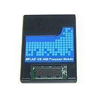
PMF18WE1
Description
PROCESSOR MODULE FOR ICE4000
Manufacturer
Microchip Technology
Datasheet
1.ICE4000.pdf
(98 pages)
Specifications of PMF18WE1
Module/board Type
Processor Module
Product
Microcontroller Modules
Core Processor
PIC18F6585/6680/8585/8680
Lead Free Status / RoHS Status
Contains lead / RoHS non-compliant
For Use With/related Products
ICE4000
Lead Free Status / RoHS Status
Lead free / RoHS Compliant, Contains lead / RoHS non-compliant


4.6
4.7
2004 Microchip Technology Inc.
USING HARDWARE BREAKPOINTS
USING TRIGGER IN/OUT SETTINGS
In addition to setting software breakpoints on program memory addresses, hardware
breakpoints may be set with more complex conditions. Also, hardware breakpoints can
be used to capture real-time events.
With a hardware breakpoint, execution halt may skid, or one or more additional
instructions may be executed past the set breakpoint before the processor halts.
Hardware breakpoints are set using the complex trigger. The complex trigger can be
set up to require that up to four events occur before a break (or trace) occurs. The
combination of these events can be specified three ways:
• Sequential
• All Events
• Any Event
In addition, the complex triggering feature along with the trace memory window can be
used to perform the following functions:
• Time Between Events
• Filter Trace
Complex trigger breakpoints can then be selectively enabled and disabled. Breakpoints
set in this manner are retained with the project.
Select Debugger>Complex Triggers and Code Coverage and click on the Complex
Trigger Settings tab.
For more information on complex triggering, as well as complex triggering examples,
see Chapter 6. “Complex and Internal Triggers”.
MPLAB ICE 4000 offers the following external input and output options:
• Generate a single pulse of nonspecific duration, either on the final trigger event or
• Break on a specified edge of an external trigger input.
• Freeze the trace buffer on the rising edge of the external trigger input.
These options are set through the Trigger In/Out Settings dialog (via
Debugger>Complex Triggers and Code Coverage, Trigger In/Out Settings tab). Trigger
In/Out Settings can be used with the logic probes (Section B.7 “Logic Probes”).
on a filtered trace event. Use the positive edge to trigger other equipment.
Basic Features
DS51490A-page 23
Related parts for PMF18WE1
Image
Part Number
Description
Manufacturer
Datasheet
Request
R

Part Number:
Description:
Manufacturer:
Microchip Technology Inc.
Datasheet:
Part Number:
Description:
Manufacturer:
Microchip Technology Inc.
Datasheet:
Part Number:
Description:
Manufacturer:
Microchip Technology Inc.
Datasheet:
Part Number:
Description:
Manufacturer:
Microchip Technology Inc.
Datasheet:
Part Number:
Description:
Manufacturer:
Microchip Technology Inc.
Datasheet:
Part Number:
Description:
Manufacturer:
Microchip Technology Inc.
Datasheet:
Part Number:
Description:
Manufacturer:
Microchip Technology Inc.
Datasheet:
Part Number:
Description:
Manufacturer:
Microchip Technology Inc.
Datasheet: