PMF18WD1 Microchip Technology, PMF18WD1 Datasheet - Page 40
PMF18WD1
Manufacturer Part Number
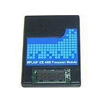
PMF18WD1
Description
PROCESSOR MODULE FOR ICE4000
Manufacturer
Microchip Technology
Datasheet
1.ICE4000.pdf
(98 pages)
Specifications of PMF18WD1
Module/board Type
Processor Module
Product
Microcontroller Modules
Core Processor
PIC18F1310 and PIC18F1320
Lead Free Status / RoHS Status
Contains lead / RoHS non-compliant
For Use With/related Products
ICE4000
For Use With
ICE4000 - EMULATOR MPLAB-ICE 4000 POD
Lead Free Status / RoHS Status
Lead free / RoHS Compliant, Contains lead / RoHS non-compliant


MPLAB
DS51490A-page 34
ICE 4000 User’s Guide
Figure 6-1 shows what the tab will look like for a sequential event and program memory
selection. This is the typical layout of the Complex Trigger Settings tab.
FIGURE 6-1:
For information on trigger type (event) selection, see Section 6.6 “Trigger Type
Selection”.
Trace-related trigger information may be entered in the following items:
• Trigger Position – Used to position the trigger location in the trace memory
• Halt On Trigger – The trigger point will generate a hardware breakpoint, halting
• Halt On Cycles After Trigger – The trigger point will not generate a hardware
• Halt On Trace Buffer Full – A trigger will cause the trace buffer to stop before
• Ignore FNOP Cycles – Specifies whether or not forced NOP cycles are to be
window, indicating the number of cycles captured by the trace memory window
after the trigger occurs (Cycles Traced After Trigger). The approximate cycle that
generated the trigger will be indicated with an arrow.
the processor, and will be the last entry in the trace memory window. To capture
traces without halting the target, unselect this option.
breakpoint until the Cycles Traced After Trigger is reached. Then the processor
will be halted. To capture traces without halting the target, unselect this option.
overwriting old data. When the trace buffer is full (64K-1 or 65535 entries), a
hardware breakpoint will halt the processor.
considered in the event processing. A forced NOP cycle is the second cycle of a
two-cycle instruction. Since the PICmicro
prefetches the next instruction in the physical address space while it is executing
the current instruction. However, if the current instruction changes the program
counter, this prefetched instruction is explicitly ignored, causing a forced NOP
cycle.
Note: The number of downloaded lines specified in the Configure Trace tab does
not affect the number of cycles collected, and Trigger Position still applies.
1
COMPLEX TRIGGER – PROGRAM MEMORY, SEQUENTIAL
2
®
MCU architecture is pipelined, it
2004 Microchip Technology Inc.
Related parts for PMF18WD1
Image
Part Number
Description
Manufacturer
Datasheet
Request
R

Part Number:
Description:
Manufacturer:
Microchip Technology Inc.
Datasheet:
Part Number:
Description:
Manufacturer:
Microchip Technology Inc.
Datasheet:
Part Number:
Description:
Manufacturer:
Microchip Technology Inc.
Datasheet:
Part Number:
Description:
Manufacturer:
Microchip Technology Inc.
Datasheet:
Part Number:
Description:
Manufacturer:
Microchip Technology Inc.
Datasheet:
Part Number:
Description:
Manufacturer:
Microchip Technology Inc.
Datasheet:
Part Number:
Description:
Manufacturer:
Microchip Technology Inc.
Datasheet:
Part Number:
Description:
Manufacturer:
Microchip Technology Inc.
Datasheet: