PMF18WD1 Microchip Technology, PMF18WD1 Datasheet - Page 19
PMF18WD1
Manufacturer Part Number
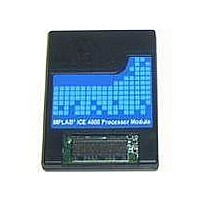
PMF18WD1
Description
PROCESSOR MODULE FOR ICE4000
Manufacturer
Microchip Technology
Datasheet
1.ICE4000.pdf
(98 pages)
Specifications of PMF18WD1
Module/board Type
Processor Module
Product
Microcontroller Modules
Core Processor
PIC18F1310 and PIC18F1320
Lead Free Status / RoHS Status
Contains lead / RoHS non-compliant
For Use With/related Products
ICE4000
For Use With
ICE4000 - EMULATOR MPLAB-ICE 4000 POD
Lead Free Status / RoHS Status
Lead free / RoHS Compliant, Contains lead / RoHS non-compliant


2.8
2004 Microchip Technology Inc.
SOFTWARE SETUP
1. Launch MPLAB IDE v6.xx.
2. From the Configure menu, select Select Device. In this dialog, choose the device
3. From the Debugger menu, select Select Tool and then MPLAB ICE 4000 to
4. The default port setting is USB = ICEUSB-0. If you wish to change this settings,
5. MPLAB ICE 4000 allows the emulator processor module to be powered by either
MPLAB ICE 4000 should now be ready for you to use as an emulator. If you have had
problems, please consult Appendix A. “Troubleshooting”. Otherwise, proceed to the
next chapter for additional software setup considerations.
you will be emulating and click OK.
enable the emulator.
Once you have selected MPLAB ICE 4000, debug options will appear on the
Debugger menu.
you may do so on the Port tab of the Debugger>Settings dialog. See
Section 3.4 “Configuring the Communications Port” for more information.
the emulator pod or the target system. This is set up in MPLAB IDE as follows:
• Emulator pod: Debugger>Settings, Power tab, “Processor Power From
• Target system: Debugger>Settings, Power tab, “Processor Power From
See Section 3.5 “Selecting Processor Power” for more information. Also,
refer to the MPLAB ICE 4000 Processor Module and Device Adapter Specifica-
tion for processor module power requirements before configuring the system for
target system power.
When connecting to a target application system, you may notice a voltage level
on the target application, even though you have not yet applied power to the tar-
get application circuit. This is normal and is due to current leakage of protection
diodes through V
less than 20 mA. However, if the target application is using a voltage regulator, it
should be noted that some regulators require the use of an external shunt diode
between V
data sheets for additional information.
Emulator”
Target Board”
Note: If you cannot select the emulator as the debug tool, please see
Note: It is recommended that you not have a programmer enabled at the
Note: You must select “Processor Power From Target Board” when using
IN
Appendix A. “Troubleshooting”.
same time as the emulator. See Appendix A. “Troubleshooting” for
more information.
low-voltage emulation.
and V
CC
OUT
of the Device Adapter. The current leakage will typically be
for reverse-bias protection. Refer to the manufacture’s
Installation
DS51490A-page 13
Related parts for PMF18WD1
Image
Part Number
Description
Manufacturer
Datasheet
Request
R

Part Number:
Description:
Manufacturer:
Microchip Technology Inc.
Datasheet:
Part Number:
Description:
Manufacturer:
Microchip Technology Inc.
Datasheet:
Part Number:
Description:
Manufacturer:
Microchip Technology Inc.
Datasheet:
Part Number:
Description:
Manufacturer:
Microchip Technology Inc.
Datasheet:
Part Number:
Description:
Manufacturer:
Microchip Technology Inc.
Datasheet:
Part Number:
Description:
Manufacturer:
Microchip Technology Inc.
Datasheet:
Part Number:
Description:
Manufacturer:
Microchip Technology Inc.
Datasheet:
Part Number:
Description:
Manufacturer:
Microchip Technology Inc.
Datasheet: