ATAVRSB100 Atmel, ATAVRSB100 Datasheet - Page 5
ATAVRSB100
Manufacturer Part Number
ATAVRSB100
Description
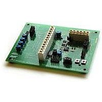
SMART BATTERY DEVELOPMENT KIT
Manufacturer
Atmel
Type
Smart Batteryr
Datasheet
1.ATAVRSB100.pdf
(20 pages)
Specifications of ATAVRSB100
Contents
Fully Assembled Evaluation Board
Processor
ATmega406
Processor To Be Evaluated
ATmega406
Data Bus Width
8 bit
Interface Type
JTAG
For Use With/related Products
ATmega406
Lead Free Status / RoHS Status
Contains lead / RoHS non-compliant
Other names
Q2367281


2.1.4 Wiring for live Li-Ion battery cells
2598C-AVR-06/06
Figure 2-3. CONN2 wiring and jumper settings for battery simulation
Table 2-4. JB3: Cell voltage simulation jumper block
Normal cell wiring is shown on the SB100 board, labeled as such. The ATmega406
supports from two to four stacked Li-Ion cells. As many cells as required may be
connected in parallel. A jumper should always connect CELL1- (CONN2 pin 8) to
Sense Resistor High (CONN2 pin 9) to enable the current-sense resistor. Cells
should always be connected on the lower positions first. The FET connection
(CONN2 pin 3) should be tied to the most positive cell connection (either CELL4+,
CELL3+ or CELL2+).
When using live cells, all jumpers should be removed from JB3. Additionally, the
sense resistor should be connected to the CCADC inputs by shorting JB4 pins 1-3
and 2-4. It is possible to use the Current Simulator while connected to live cells simply
WARNING:
Pin
1
2
3
4
5
6
7
8
9
10
24V
±5V
Name
SIM-CELL4+
CELL4+
SIM-CELL3+
CELL3+
SIM-CELL2+
CELL2+
SIM-CELL1+
CELL1+
SIM-CELL1-
CELL1-
+
-
When using live cells, never leave the system unattended due to the potential
hazards associated with the use of Li-Ion cells. Do not apply high charging or
discharging currents to the cells until you have verified that all safety systems,
both hardware and software, are functional under the specified conditions.
CONN2
Direction
V-SIM GND
V-SIM +24V
FETs
GND
I-SIM +/-5V
I-SIM Gnd
Usage
Short these two pins to connected
simulated CELL4+ to smart Battery
Short these two pins to connected
simulated CELL3+ to smart Battery
Short these two pins to connected
simulated CELL2+ to smart battery
Short these two pins to connected
simulated CELL1+ to smart battery
Short these two pins to connected
simulated CELL1- to smart battery
1
JB3
1
JB4
AVR454
J1
5
Related parts for ATAVRSB100
Image
Part Number
Description
Manufacturer
Datasheet
Request
R

Part Number:
Description:
DEV KIT FOR AVR/AVR32
Manufacturer:
Atmel
Datasheet:

Part Number:
Description:
INTERVAL AND WIPE/WASH WIPER CONTROL IC WITH DELAY
Manufacturer:
ATMEL Corporation
Datasheet:
Part Number:
Description:
Low-Voltage Voice-Switched IC for Hands-Free Operation
Manufacturer:
ATMEL Corporation
Datasheet:
Part Number:
Description:
MONOLITHIC INTEGRATED FEATUREPHONE CIRCUIT
Manufacturer:
ATMEL Corporation
Datasheet:
Part Number:
Description:
AM-FM Receiver IC U4255BM-M
Manufacturer:
ATMEL Corporation
Datasheet:
Part Number:
Description:
Monolithic Integrated Feature Phone Circuit
Manufacturer:
ATMEL Corporation
Datasheet:
Part Number:
Description:
Multistandard Video-IF and Quasi Parallel Sound Processing
Manufacturer:
ATMEL Corporation
Datasheet:
Part Number:
Description:
High-performance EE PLD
Manufacturer:
ATMEL Corporation
Datasheet:
Part Number:
Description:
8-bit Flash Microcontroller
Manufacturer:
ATMEL Corporation
Datasheet:
Part Number:
Description:
2-Wire Serial EEPROM
Manufacturer:
ATMEL Corporation
Datasheet: