DM300014 Microchip Technology, DM300014 Datasheet - Page 49
DM300014
Manufacturer Part Number
DM300014
Description
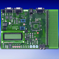
BOARD DEMO DSPICDEM 1.1 GEN PURP
Manufacturer
Microchip Technology
Datasheet
1.DM300014.pdf
(72 pages)
Specifications of DM300014
Processor To Be Evaluated
PIC30F
Data Bus Width
16 bit
Interface Type
RS-485, CAN, SPI
Lead Free Status / RoHS Status
Lead free / RoHS Compliant
Lead Free Status / RoHS Status
Lead free / RoHS Compliant, Lead free / RoHS Compliant


2003 Microchip Technology Inc.
4.1.12
Headers J11 and J13-J15 provide a connection to the MPLAB ICE 4K In-Circuit
Emulator. The emulation headers also support Plug-in Modules containing dsPIC30F
devices soldered onto adaptor boards (see Section 4.1.18). These Plug-in Modules
facilitate quick change out of the 80-pin TQFP device.
The schematic of the Emulation Header is shown in Figure A-3: “dsPICDEM 1.1
Development Board Schematic (Sheet 2 of 5)”.
4.1.13
The dsPICDEM 1.1 is powered by a +9V AC/DC wall adapter. Separate +5V DC
regulators (V
prototyping area. Separate ground planes are connected through a single point.
Jumpers VDD_JMP and AVDD_JMP allow the supplied power source to be bypassed
and alternate supplies to be provided.
The schematics of the power supply circuits are shown in Figure A-3: “dsPICDEM 1.1
Development Board Schematic (Sheet 2 of 5)”.
4.1.14
A green LED is connected to the input of the regulators to indicate the presence of
power. See Figure A-3: “dsPICDEM 1.1 Development Board Schematic (Sheet 2
of 5)”.
4.1.15
• Crystal oscillator (7.3728 MHz) is supplied with the development board.
• Through holes and pads are provided for a user-furnished watch-type crystal and
• Socket and pads are provided for an output pull-up resistor for user furnished
• External clock connections from J1.
Oscillator selection parameters are shown in Table 4-2.
TABLE 4-2:
Crystal (X3)
Mini Crystal (X2)
Canned Oscillator (U5)
RC
External Clock
The oscillator circuit schematics are shown in Figure A-2: “dsPICDEM 1.1
Development Board Schematic (Sheet 1 of 5)”
two capacitors for SOSC1 and SOSC2.
oscillator to processor.
dsPICDEM 1.1 Demo Board
Oscillator Selection on
dsPICDEM™ 1.1 Development Hardware
Emulation Header
Power Supply
Power-on Indicator
Oscillator Options
DD
and AV
OSCILLATOR SELECTION PARAMETERS
Advance Information
DD
) are provided to their respective processor pins and
R33, R34, R20, C20, C21 and X2 open, U5 empty.
Crystal in X3, caps in C33 and C37.
R20, R33, R34, C33, C37 and X1 open, U5 empty.
Crystal in X2, caps in C20 and C21.
R20, R33, R34, C20, C21, C33, C37, X2 and X3 open,
U5 installed.
R33, R34, C20, C21, C33, X2 and X3 open, U5 empty.
Cap in C37 and resistor in R20.
R20, C20, C21, C33, C37, U5, X2 and X3 open. 0 ohm
installed for R33 and R34.
Modifications on dsPICDEM 1.1 Demo Board
DS70099B-page 45
Related parts for DM300014
Image
Part Number
Description
Manufacturer
Datasheet
Request
R

Part Number:
Description:
Manufacturer:
Microchip Technology Inc.
Datasheet:
Part Number:
Description:
Manufacturer:
Microchip Technology Inc.
Datasheet:
Part Number:
Description:
Manufacturer:
Microchip Technology Inc.
Datasheet:
Part Number:
Description:
Manufacturer:
Microchip Technology Inc.
Datasheet:
Part Number:
Description:
Manufacturer:
Microchip Technology Inc.
Datasheet:
Part Number:
Description:
Manufacturer:
Microchip Technology Inc.
Datasheet:
Part Number:
Description:
Manufacturer:
Microchip Technology Inc.
Datasheet:
Part Number:
Description:
Manufacturer:
Microchip Technology Inc.
Datasheet: