DM300014 Microchip Technology, DM300014 Datasheet - Page 48
DM300014
Manufacturer Part Number
DM300014
Description
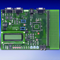
BOARD DEMO DSPICDEM 1.1 GEN PURP
Manufacturer
Microchip Technology
Datasheet
1.DM300014.pdf
(72 pages)
Specifications of DM300014
Processor To Be Evaluated
PIC30F
Data Bus Width
16 bit
Interface Type
RS-485, CAN, SPI
Lead Free Status / RoHS Status
Lead free / RoHS Compliant
Lead Free Status / RoHS Status
Lead free / RoHS Compliant, Lead free / RoHS Compliant


dsPICDEM™ 1.1 Development Board User’s Guide
DS70099B-page 44
4.1.8
A single channel digital potentiometer, MCP41010, is provided on the development
board. Control of the digital potentiometer is via the dsPIC SPI 2 communication
channel. The output of the digital potentiometer is applied to a low-pass filter with a
cut-off frequency of approximately 4 kHz. The output of the LP filter is connected to the
analog channel AN3 of the dsPIC device.
The schematic of the digital potentiometers is shown in Figure A-6: “dsPICDEM 1.1
Development Board Schematic (Sheet 5 of 5)”.
4.1.9
The LCD graphic display is a PG12232D-L 8-bit 122 x 32 dot-matrix LCD controlled by
a PIC18F242 LCD controller. The dsPIC30F device accesses the LCD controller via
the SPI 2 port. For a detailed description of the communication protocol, see Appendix
B. “LCD Controller Specification”.
The LCD PIC18F242 controller is reset by setting jumper J10 to the MCLR2 position
and pressing the Reset switch. Moving jumper J10 back to the MCLR1 position returns
RESET control of the dsPIC30F device.
The schematic of the analog potentiometers is shown in Figure A-5: “dsPICDEM 1.1
Development Board Schematic (Sheet 4 of 5)”.
4.1.10
By way of the modular connector ICD, the MPLAB ICD 2 can be connected for low-cost
programming and debugging of the dsPIC device. Programming and debugging the
dsPIC device requires that jumper J8 is set to the PGC/EMUC and PGD/EMUD
position and jumper J10 is set to the MCLR1 position. Programming the PIC18F242
LCD controller requires that jumper J8 is set to the RB6/242 and RB7/242 position and
jumper J10 is set to the MCLR2 position.
The PIC18F242 LCD controller is programmed at the factory with the LCD driver code.
Under normal operating conditions, no additional programming should be required for
this device.
The schematic of the analog potentiometers is shown in Figure A-5: “dsPICDEM 1.1
Development Board Schematic (Sheet 4 of 5)”
4.1.11
An Si3000 Codec from Silicon Labs is included on the development board. Stereo
Jacks provide MIC input on J16 and SPKR OUT output on J17. LINE I/O on J12
provides line-in and line-out connections. J9 provides a selection for Master or Slave
operation for the Si3000. When the Si3000 is operated in Master mode, the user must
provide a suitable clock oscillator in the U6 socket. The CODEC RESET switch resets
the Si3000.
For detailed operational information, refer to the Si3000 data sheet available on
www.silabs.com. For a schematic of the Si3000 circuit, see Figure A-5: “dsPICDEM
1.1 Development Board Schematic (Sheet 4 of 5)”.
Digital Potentiometer
LCD Graphic Display
ICD Connector
Si3000 Voice-band Codec
Advance Information
2003 Microchip Technology Inc.
Related parts for DM300014
Image
Part Number
Description
Manufacturer
Datasheet
Request
R

Part Number:
Description:
Manufacturer:
Microchip Technology Inc.
Datasheet:
Part Number:
Description:
Manufacturer:
Microchip Technology Inc.
Datasheet:
Part Number:
Description:
Manufacturer:
Microchip Technology Inc.
Datasheet:
Part Number:
Description:
Manufacturer:
Microchip Technology Inc.
Datasheet:
Part Number:
Description:
Manufacturer:
Microchip Technology Inc.
Datasheet:
Part Number:
Description:
Manufacturer:
Microchip Technology Inc.
Datasheet:
Part Number:
Description:
Manufacturer:
Microchip Technology Inc.
Datasheet:
Part Number:
Description:
Manufacturer:
Microchip Technology Inc.
Datasheet: