DM300014 Microchip Technology, DM300014 Datasheet - Page 40
DM300014
Manufacturer Part Number
DM300014
Description
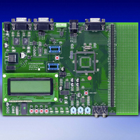
BOARD DEMO DSPICDEM 1.1 GEN PURP
Manufacturer
Microchip Technology
Datasheet
1.DM300014.pdf
(72 pages)
Specifications of DM300014
Processor To Be Evaluated
PIC30F
Data Bus Width
16 bit
Interface Type
RS-485, CAN, SPI
Lead Free Status / RoHS Status
Lead free / RoHS Compliant
Lead Free Status / RoHS Status
Lead free / RoHS Compliant, Lead free / RoHS Compliant


dsPICDEM™ 1.1 Development Board User’s Guide
DS70099B-page 36
3.4.3
3.4.3.1
External interrupts INT1-INT4 are controlled by switches SW1-SW4.
These switches provide selection capabilities for the demo program. The most recent
switch presses are recorded in a variable within the interrupt routines. In the main
routine, the variable is analyzed to determine what action is requested by the recent
switch event.
3.4.3.2
The DCI module interrupts the CPU when all four TXBUF registers have been
transmitted. The DCI is used to send out DTMF tones to the Codec. The tonal
components are stored as sinusoid tables in program memory and accessed using
Program Space Visibility (PSV).
The DCI ISR keeps track of the number of samples sent. The DTMF tones are
transmitted by adhering to International Telecommunication Union (ITU-T)
specifications. For example, the ON time for tones is greater than 40 mS and the OFF
time is less than 23 mS. The actual values are 100 mS of ON time and 15 mS of OFF
time. When playing a pre-recorded sequence of tones, a PAUSE time is added
between successive tones. This time is equal to the ON time of the tone. Also, the high
and low frequency of the DTMF tone are separated by 8 dB. The high frequencies are
reduced in magnitude relative to the low frequencies by 8 dB.
3.4.3.3
Single DTMF tones may also be played by entering numeric characters (0-9) on the PC
keyboard during the HyperTerminal session. The UART receives this keyboard
character, and a receiver interrupt communicates this data to the DCI to start a tone
generation process.
3.4.3.4
Every 1.14 seconds, data is transmitted via the UART to the HyperTerminal session
window. Four bytes are loaded at a time in the Transmitter Buffer registers. The term
“data” refers to the following:
• Analog data such as RP1, RP2 and RP3
• Temperature sensor data
• FFT frequency and bin number of the sampled input sinewave signal
• Cycle count information for the FFT, FIR or IIR algorithms
• Chosen Filter Type – IIR, FIR or None
3.4.3.5
The SPI 2 module is used to perform two functions:
• When the demo code is waiting for the A/D converter to collect 256 samples of
• When code execution reaches the DSP stage (i.e., filtering, FFT etc.) the SPI 2
data on pin AN3, the SPI 2 module is used by the Timer1 ISR to transmit
sine-wave samples to the MCP41010 every 125 microseconds at a data rate of
230 kHz.
module is used to send data to the PIC18F242 LCD controller on the expansion
board at a data rate of 921.6 KHz (F
display. All 80 characters are refreshed by the SPI 2 module.
Interrupts Used in the Demo
EXTERNAL INTERRUPTS TO MAIN ROUTINE
DCI INTERRUPTS AND DTMF
UART RECEIVE INTERRUPTS
UART TRANSMIT INTERRUPTS
SPI INTERRUPTS, DIGITAL POT AND THE LCD CONTROLLER
Advance Information
CY
/8). The LCD has a 4 row x 20-character
2003 Microchip Technology Inc.
Related parts for DM300014
Image
Part Number
Description
Manufacturer
Datasheet
Request
R

Part Number:
Description:
Manufacturer:
Microchip Technology Inc.
Datasheet:
Part Number:
Description:
Manufacturer:
Microchip Technology Inc.
Datasheet:
Part Number:
Description:
Manufacturer:
Microchip Technology Inc.
Datasheet:
Part Number:
Description:
Manufacturer:
Microchip Technology Inc.
Datasheet:
Part Number:
Description:
Manufacturer:
Microchip Technology Inc.
Datasheet:
Part Number:
Description:
Manufacturer:
Microchip Technology Inc.
Datasheet:
Part Number:
Description:
Manufacturer:
Microchip Technology Inc.
Datasheet:
Part Number:
Description:
Manufacturer:
Microchip Technology Inc.
Datasheet: