DM300014 Microchip Technology, DM300014 Datasheet - Page 32
DM300014
Manufacturer Part Number
DM300014
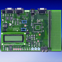
Description
BOARD DEMO DSPICDEM 1.1 GEN PURP
Manufacturer
Microchip Technology
Datasheet
1.DM300014.pdf
(72 pages)
Specifications of DM300014
Processor To Be Evaluated
PIC30F
Data Bus Width
16 bit
Interface Type
RS-485, CAN, SPI
Lead Free Status / RoHS Status
Lead free / RoHS Compliant
Lead Free Status / RoHS Status
Lead free / RoHS Compliant, Lead free / RoHS Compliant


dsPICDEM™ 1.1 Development Board User’s Guide
DS70099B-page 28
FIGURE 3-2:
From this menu you can choose one of three demonstration modes:
• Data Acquisition Display mode
• Digital Signal Processing (DSP) Operations mode
• Dual Tone Multi-Frequency (DTMF) Generation mode
3.3.1.1
The Data Acquisition Display mode demonstrates the capability of the dsPIC30F
device to convert inputs from five different analog signal sources at varying sampling
rates.
Data Acquisition mode is initiated by pressing switch SW2. Figure 3-3 shows the
resulting display on the LCD.
FIGURE 3-3:
This display shows the values of the following analog signal sources:
• Potentiometers RP1-RP3
• Temperature Sensor U2:
• Frequency:
The 12-bit A/D converter on the dsPIC30F device is used to convert these analog input
sources.
To estimate the frequency of the generated sine-wave signal, the program converts and
buffers 256 samples of the signal on pin AN3 and then performs a Fast-Fourier
Transform (FFT) on the buffer. The A/D converter is interrupt driven to sample and
convert at an 8 kHz rate for this operation.
The program scans input pins AN4, AN5, AN6 and AN8 to sample and convert the
values of the temperature sensor and potentiometer signals and delivers one sample
of each of these signals to the LCD display.
The three potentiometers available on the dsPICDEM 1.1 Development Board,
RP1, RP2 and RP3, are connected to analog input pins AN6, AN4 and AN5,
respectively, on the dsPIC30F device.
Temperature sensor, TC1047A, is connected to the analog input pin, AN8, on the
dsPIC30F device.
A fundamental sinewave signal is generated by stepping the MCP41010 digital
potentiometer (U9) output at an 8 kHz rate. The analyzed frequency is displayed
on the LCD.
DATA ACQUISITION DISPLAY MODE
Advance Information
DEMO MENU OPTIONS
DATA ACQUISITION DISPLAY
F = 1000
RP1 = 1.67
RP3 = 2.62
MAIN
D
DSP O
DTMF G
ATA
– s1
A
PERATIONS
CQ
HZ
ENERATION
M
D
ENU
V
V
ISPLAY
T
EMP
RP2 = 2.95
O
PTIONS
= +23
– S2
– S3
– S4
DG
V
C
2003 Microchip Technology Inc.
Related parts for DM300014
Image
Part Number
Description
Manufacturer
Datasheet
Request
R

Part Number:
Description:
Manufacturer:
Microchip Technology Inc.
Datasheet:
Part Number:
Description:
Manufacturer:
Microchip Technology Inc.
Datasheet:
Part Number:
Description:
Manufacturer:
Microchip Technology Inc.
Datasheet:
Part Number:
Description:
Manufacturer:
Microchip Technology Inc.
Datasheet:
Part Number:
Description:
Manufacturer:
Microchip Technology Inc.
Datasheet:
Part Number:
Description:
Manufacturer:
Microchip Technology Inc.
Datasheet:
Part Number:
Description:
Manufacturer:
Microchip Technology Inc.
Datasheet:
Part Number:
Description:
Manufacturer:
Microchip Technology Inc.
Datasheet: