8.12.00 J-LINK ARM-PRO Segger Microcontroller Systems, 8.12.00 J-LINK ARM-PRO Datasheet - Page 164
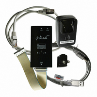
8.12.00 J-LINK ARM-PRO
Manufacturer Part Number
8.12.00 J-LINK ARM-PRO
Description
JTAG EMULATOR USB ETHERNET ARM
Manufacturer
Segger Microcontroller Systems
Type
Emulatorr
Specifications of 8.12.00 J-LINK ARM-PRO
Contents
Emulation Module
For Use With/related Products
ARM7, ARM9, ARM11, Cortex
Lead Free Status / RoHS Status
Lead free / RoHS Compliant
Other names
8.12.00 J-LINK ARM-PRO
899-1007
899-1007


164
7.5.1.2 Reset (Cortex-M3 based devices)
J-Link / J-Trace (UM08001)
With these additional commands are the values of the fast GPIO registers in the C-
SPY debugger correct and can be used for debugging. For more information about J-
Link command line options refer to subchapter Command strings on page 131.
For Cortex-M3 based NXP LPC devices the reset itself does not differ from the one for
other Cortex-M3 based devices: After the device has been reset, the core is halted
before any instruction is performed. For the Cortex-M3 based LPC devices this means
the CPU is halted before the bootloader which is mapped at address 0 after reset.
The user should write the memmap register after reset, to ensure that user flash is
mapped at address 0. Moreover, the user have to correct the Stack pointer (R13) and
the PC (R15) manually, after reset in order to debug the application.
LPC288x flash programming
In order to use the LPC288x devices in combination with J-Link FlashDL the applica-
tion you are trying to debug, should be linked to the original flash @ addr
0x10400000. Otherwise it is user’s responsibility to ensure that flash is re-mapped to
0x0 in order to debug the application from addr 0x0.
CHAPTER 7
© 2004-2011 SEGGER Microcontroller GmbH & Co. KG
Device specifics
Related parts for 8.12.00 J-LINK ARM-PRO
Image
Part Number
Description
Manufacturer
Datasheet
Request
R

Part Number:
Description:
CONNECTOR JTAG-ARM ISOLATION
Manufacturer:
Segger Microcontroller Systems
Datasheet:

Part Number:
Description:
ADAPTER ARM TARGET 14PIN RIBBON
Manufacturer:
Segger Microcontroller Systems
Datasheet:

Part Number:
Description:
JTAG EMULATOR FOR ARM CORES
Manufacturer:
Segger Microcontroller Systems
Datasheet:

Part Number:
Description:
JTAG EMULATOR FOR ARM CORES
Manufacturer:
Segger Microcontroller Systems
Datasheet:

Part Number:
Description:
PROGRAMMING TOOL FOR MCU
Manufacturer:
Segger Microcontroller Systems
Datasheet:

Part Number:
Description:
PROGRAMMING TOOL FOR ST7 MCU
Manufacturer:
Segger Microcontroller Systems
Datasheet:

Part Number:
Description:
PROGRAMMING TOOL FOR STM8
Manufacturer:
Segger Microcontroller Systems
Datasheet:

Part Number:
Description:
PROGRAMMER JTAG FOR ARM CORES
Manufacturer:
Segger Microcontroller Systems
Datasheet:

Part Number:
Description:
JTAG EMULATOR ARM7/ARM9 ETM
Manufacturer:
Segger Microcontroller Systems
Datasheet:

Part Number:
Description:
EMULATOR JTAG/SWD CORTEX M3
Manufacturer:
Segger Microcontroller Systems
Datasheet: