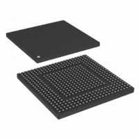
MPC8308-RDB Freescale Semiconductor, MPC8308-RDB Datasheet - Page 30

MPC8308-RDB
Manufacturer Part Number
MPC8308-RDB
Description
BOARD REF DESIGN MPC8308
Manufacturer
Freescale Semiconductor
Series
PowerQUICC II™ PROr
Type
MPUr
Datasheets
1.MPC8308VMAGD.pdf
(90 pages)
2.MPC8308VMAGD.pdf
(2 pages)
3.MPC8308-RDB.pdf
(36 pages)
4.MPC8308-RDB.pdf
(2 pages)
Specifications of MPC8308-RDB
Contents
Board, Cables, Documentation, Power Supply, Software
Ethernet Connection Type
Serial to Ethernet
Data Rate
10 Mbps, 100 Mbps, 1000 Mbps
Memory Type
DDR2, SDRAM
Interface Type
HSSI
Operating Voltage
1.5 V
Operating Current
5 uA
Maximum Power Dissipation
1000 mW
Operating Temperature Range
- 55 C to + 125 C
Product
Modules
For Use With/related Products
MPC8308
Lead Free Status / RoHS Status
Lead free / RoHS Compliant
Getting Started
supply voltage and IO supply voltages to be applied in any particular order. However, during the power
ramp up, before the power supplies are stable, there may be an interval when the IO pins are actively
driven. After the power is stable, as long as PORESET is asserted, most IO pins are three-stated. To
minimize the time that IO pins are actively driven, apply core voltage before IO voltage and assert
PORESET before the power supplies fully ramp up.
4.3
Table 11
5
This section describes how to boot the MPC8308_RDB. The on-board flash memory is preloaded with a
flash image from the factory. Before powering up the board, verify that all the on-board DIP switches and
jumpers are set to the factory defaults according to the settings listed in
Settings,”
30
0x0000_0000–0x07FF_FFFF
0xE000_0000–0xE00F_FFFF
0xE280_0000–0xE280_7FFF
0xF000_0000–0xF001_FFFF
0xFE00_0000–0xFE7F_FFFF
Voltage
1.2V
1.5V
1.5V
1.8V
2.5V
3.3V
Address Range
12V
Getting Started
1V
5V
shows an example memory map on the MPC8308_RDB for u-boot in NOR flash memory.
Chip-Select Assignments and Memory Map -TBD
Table 11. Example Memory Map, Local Access Window, and Chip-Select Assignments
and make all external connections as described in
external 12V supply of mini
mini PCIe connector
DDR2, RTL8211B
Switching power
VSC7385 core
PCIe adaptor
VSC7385 IO
General IO
RTL8211B
DDR2
Internal bus
NAND Controller LCS1#
Local bus
Local bus
Target Interface
Usage
Vcore
PowerQUICC™ MPC8308_RDB User’s Guide, Rev. 3
Table 10. Power Supply Usage Summary
MCS0#
Nil
LCS2#
LCS0#
Chip-Select
Line
Budget
TBD
TBD
TBD
TBD
TBD
TBD
TBD
TBD
TBD
DDR SDRAM (128 Mbyte)
IMMR (1 Mbyte)
NAND Flash window (32Kbyte)
VSC7385 (128Kbyte)
Boot Flash (8 Mbyte)
Section 5.2, “External Cable Connections.”
Device Name
Section 5.1, “Board Jumper
NCP 1117SRAR3G LDO (1A)
NCP 1117SRAR3G LDO (1A)
NCP 1117SRAR3G LDO (1A)
MIC1954EUB+ switching
MIC1954EUB+ switching
Direct from Power Jack
Direct from Power Jack
MIC37302 LDO (3A)
MIC37302 LDO (3A)
Solution
Micetek International Inc.
32
—
8
8
16
Port Size (Bits)


