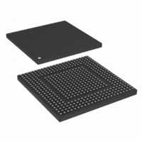
MPC8308-RDB Freescale Semiconductor, MPC8308-RDB Datasheet - Page 25

MPC8308-RDB
Manufacturer Part Number
MPC8308-RDB
Description
BOARD REF DESIGN MPC8308
Manufacturer
Freescale Semiconductor
Series
PowerQUICC II™ PROr
Type
MPUr
Datasheets
1.MPC8308VMAGD.pdf
(90 pages)
2.MPC8308VMAGD.pdf
(2 pages)
3.MPC8308-RDB.pdf
(36 pages)
4.MPC8308-RDB.pdf
(2 pages)
Specifications of MPC8308-RDB
Contents
Board, Cables, Documentation, Power Supply, Software
Ethernet Connection Type
Serial to Ethernet
Data Rate
10 Mbps, 100 Mbps, 1000 Mbps
Memory Type
DDR2, SDRAM
Interface Type
HSSI
Operating Voltage
1.5 V
Operating Current
5 uA
Maximum Power Dissipation
1000 mW
Operating Temperature Range
- 55 C to + 125 C
Product
Modules
For Use With/related Products
MPC8308
Lead Free Status / RoHS Status
Lead free / RoHS Compliant
3.10
DIP switch S1 on the board is shown in
RSVD[0:1] is reserved. When software options are implemented, its values can be read from a buffer on
the board. CFG_BOOT_ECC_DIS switch is OFF by default to disable booting with ECC by driving HIGH
to the signal LB_POR_CFG_BOOT_ECC_DIS (TSEC1_TX_ER) during power on reset. BOOT1 selects
the boot device on the RDB. By default, BOOT1 is set, so chip-select 0 (CS0) is connected to the NOR
Flash. CS1 is connected to the NAND flash memory. If BOOT1 is cleared, CS0 is connected to NAND
flash memory, and CS1 is connected to NOR flash memory.
3.11
DIP switch S2 selects the reset configuration source (RST_CFG_SRC) for the MPC8308.
the factory default configuration of S2.
Micetek International Inc.
DIP Switch S1
DIP Switch S2
Figure 22. IEEE 1588 Connector (P4) - Optional
PowerQUICC™ MPC8308_RDB User’s Guide, Rev. 3
TSEC_TMR_GCLK
TSEC_TMR_PP2
TSEC_TMR_PP3
TSEC_TMR_PP1
0
1
Figure
Figure 23. DIP Switch S1
GND
GND
GND
3.3 V
ON
1
23, with the factory default configuration.
1
2
3.3 V
TSEC_TMR_ALARM1
TSEC_TMR_ALARM2
TSEC_TMR_TRIG1
TSEC_TMR_TRIG2
TSEC_TMR_TRIG2
GND
TSEC_TMR_CLK
3
4
Connectors, Jumpers, Switches, and LEDs
Figure 24
shows
25


