AT91SAM7A1-EK Atmel, AT91SAM7A1-EK Datasheet - Page 8
AT91SAM7A1-EK
Manufacturer Part Number
AT91SAM7A1-EK
Description
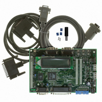
BOARD EVAL FOR AT91SAM7A1
Manufacturer
Atmel
Series
AT91SAM Smart ARMr
Type
MCUr
Datasheet
1.AT91SAM7A1-EK.pdf
(31 pages)
Specifications of AT91SAM7A1-EK
Contents
Evaluation Board, Parallel Cable and CD-ROM
Processor To Be Evaluated
AT91SAM7A1
Data Bus Width
32 bit
Interface Type
RS-232
For Use With/related Products
AT91SAM7A1
Lead Free Status / RoHS Status
Contains lead / RoHS non-compliant
Available stocks
Company
Part Number
Manufacturer
Quantity
Price
Company:

Part Number:
AT91SAM7A1-EK
Manufacturer:
Atmel
Quantity:
2


6114A–ATARM–09/04
2.4
2.5
2.6
2-2
Voltage
Powering Up the
Board
Measuring
Current
Consumption on
the AT91SAM7A1
DC power is supplied to the board via the 2.1 mm connector (J1) shown in Figure 2-2.
The polarity of the power supply is not critical. The minimum voltage required is 7V. The
supply must be isolated from ground. The 0 volts of the on-board regulated supplies can
be connected to ground via any one of the 4 test points, TP1 to TP4.
Figure 2-2. 2.1mm Connector
The board has a voltage regulator providing +3.3V and another providing +5V. These
regulators allow the input voltage to be from 7V to 12V.
Figure 2-3. Powering Up the Board
The board is designed to generate the entire power supply of the AT91SAM7A1 device.
The PCB power tracks to the ARM7 core, the I/O and the analog cells are independent.
This feature enables measurement of the current consumption of the different major
parts of the AT91SAM7A1 device.
Table 2-1. Current Consumption Measurement Procedure
Block to Measure
Analog Cells
I/O Cells
Core
The red LED marked
"DS1" lights up
Switch the
power on
End
Yes
Strap to Unsolder
No
AT91SAM7A1-EK Evaluation Board User Guide
E1
E2
E3
Positive (+) or
Negative(-)
Switch off, check the
supply connections
fuse and the power
Connect an ammeter in place
of the strap
Action
Related parts for AT91SAM7A1-EK
Image
Part Number
Description
Manufacturer
Datasheet
Request
R

Part Number:
Description:
MCU ARM9 64K SRAM 144-LFBGA
Manufacturer:
Atmel
Datasheet:

Part Number:
Description:
IC ARM7 MCU FLASH 256K 100LQFP
Manufacturer:
Atmel
Datasheet:

Part Number:
Description:
IC ARM9 MPU 217-LFBGA
Manufacturer:
Atmel
Datasheet:
Part Number:
Description:
MCU ARM9 ULTRA LOW PWR 217-LFBGA
Manufacturer:
Atmel
Datasheet:

Part Number:
Description:
MCU ARM9 324-TFBGA
Manufacturer:
Atmel
Datasheet:
Part Number:
Description:
IC MCU ARM9 SAMPLING 217CBGA
Manufacturer:
Atmel
Datasheet:
Part Number:
Description:
IC ARM9 MCU 217-LFBGA
Manufacturer:
Atmel
Datasheet:

Part Number:
Description:
IC ARM9 MCU 208-PQFP
Manufacturer:
Atmel
Datasheet:
Part Number:
Description:
MCU ARM 512K HS FLASH 100-LQFP
Manufacturer:
Atmel
Datasheet:

Part Number:
Description:
MCU ARM 512K HS FLASH 100-TFBGA
Manufacturer:
Atmel
Datasheet:
Part Number:
Description:
IC ARM9 MCU 200 MHZ 324-TFBGA
Manufacturer:
Atmel
Datasheet:

Part Number:
Description:
IC ARM MCU 16BIT 128K 256BGA
Manufacturer:
Atmel
Datasheet:

Part Number:
Description:
IC ARM7 MCU 32BIT 128K 64LQFP
Manufacturer:
Atmel
Datasheet:

Part Number:
Description:
IC ARM7 MCU FLASH 256K 128-LQFP
Manufacturer:
Atmel
Datasheet:
Part Number:
Description:
IC ARM7 MCU FLASH 512K 128-LQFP
Manufacturer:
Atmel
Datasheet: