MPC8360E-RDK Freescale Semiconductor, MPC8360E-RDK Datasheet - Page 100
MPC8360E-RDK
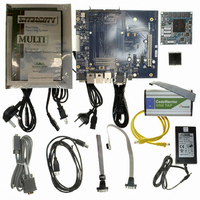
Manufacturer Part Number
MPC8360E-RDK
Description
BOARD REFERENCE DESIGN FOR MPC
Manufacturer
Freescale Semiconductor
Series
PowerQUICC II™ PROr
Type
MPUr
Specifications of MPC8360E-RDK
Contents
Board, Cables, CD, Power Supply
Processor To Be Evaluated
MPC8360E
Data Bus Width
32 bit
Interface Type
RS-232, Ethernet, USB
Operating Supply Voltage
1.3 V
For Use With/related Products
MPC8360E
Lead Free Status / RoHS Status
Lead free / RoHS Compliant


Thermal
R
change the case-to-ambient thermal resistance, R
sink, the airflow around the device, the interface material, the mounting arrangement on printed-circuit
board, or change the thermal dissipation on the printed-circuit board surrounding the device.
To illustrate the thermal performance of the devices with heat sinks, the thermal performance has been
simulated with a few commercially available heat sinks. The heat sink choice is determined by the
application environment (temperature, airflow, adjacent component power dissipation) and the physical
space available. Because there is not a standard application environment, a standard heat sink is not
required.
Table 78
AAVID 30 × 30 × 9.4 mm pin fin
AAVID 30 × 30 × 9.4 mm pin fin
AAVID 30 × 30 × 9.4 mm pin fin
AAVID 31 × 35 × 23 mm pin fin
AAVID 31 × 35 × 23 mm pin fin
AAVID 31 × 35 × 23 mm pin fin
Wakefield, 53 × 53 × 25 mm pin fin
Wakefield, 53 × 53 × 25 mm pin fin
Wakefield, 53 × 53 × 25 mm pin fin
MEI, 75 × 85 × 12 no adjacent board, extrusion
MEI, 75 × 85 × 12 no adjacent board, extrusion
MEI, 75 × 85 × 12 no adjacent board, extrusion
MEI, 75 × 85 × 12 mm, adjacent board, 40 mm side bypass
Accurate thermal design requires thermal modeling of the application environment using computational
fluid dynamics software which can model both the conduction cooling and the convection cooling of the
air moving through the application. Simplified thermal models of the packages can be assembled using the
junction-to-case and junction-to-board thermal resistances listed in the thermal resistance table. More
detailed thermal models can be made available on request.
100
θ
JC
MPC8360E/MPC8358E PowerQUICC II Pro Processor Revision 2.x TBGA Silicon Hardware Specifications, Rev. 4
is device related and cannot be influenced by the user. The user controls the thermal environment to
R
R
θ
θ
shows heat sinks and junction-to-ambient thermal resistance for TBGA package.
JC
CA
Table 78. Heat Sinks and Junction-to-Ambient Thermal Resistance of TBGA Package
Heat Sink Assuming Thermal Grease
= junction-to-case thermal resistance (°C/W)
= case-to-ambient thermal resistance (°C/W)
θ
CA
. For instance, the user can change the size of the heat
Natural convention
Natural convention
Natural convention
Natural convention
Airflow
1 m/s
2 m/s
1 m/s
2 m/s
1 m/s
2 m/s
1 m/s
2 m/s
1 m/s
Freescale Semiconductor
Junction-to-Ambient
Thermal Resistance
35 × 35 mm TBGA
10.7
6.2
5.3
8.1
4.4
3.7
5.4
3.2
2.4
6.4
3.8
2.5
2.8
Related parts for MPC8360E-RDK
Image
Part Number
Description
Manufacturer
Datasheet
Request
R

Part Number:
Description:
Mpc8360e Powerquicc Ii Pro Family
Manufacturer:
Freescale Semiconductor, Inc
Datasheet:

Part Number:
Description:
BOARD PROCESSOR FOR MPC8360E
Manufacturer:
Freescale Semiconductor
Datasheet:
Part Number:
Description:
Manufacturer:
Freescale Semiconductor, Inc
Datasheet:
Part Number:
Description:
Manufacturer:
Freescale Semiconductor, Inc
Datasheet:
Part Number:
Description:
Manufacturer:
Freescale Semiconductor, Inc
Datasheet:
Part Number:
Description:
Manufacturer:
Freescale Semiconductor, Inc
Datasheet:
Part Number:
Description:
Manufacturer:
Freescale Semiconductor, Inc
Datasheet:
Part Number:
Description:
Manufacturer:
Freescale Semiconductor, Inc
Datasheet:
Part Number:
Description:
Manufacturer:
Freescale Semiconductor, Inc
Datasheet:
Part Number:
Description:
Manufacturer:
Freescale Semiconductor, Inc
Datasheet:
Part Number:
Description:
Manufacturer:
Freescale Semiconductor, Inc
Datasheet:
Part Number:
Description:
Manufacturer:
Freescale Semiconductor, Inc
Datasheet:
Part Number:
Description:
Manufacturer:
Freescale Semiconductor, Inc
Datasheet:
Part Number:
Description:
Manufacturer:
Freescale Semiconductor, Inc
Datasheet:
Part Number:
Description:
Manufacturer:
Freescale Semiconductor, Inc
Datasheet: