M5211DEMO Freescale Semiconductor, M5211DEMO Datasheet - Page 8
M5211DEMO
Manufacturer Part Number
M5211DEMO
Description
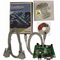
KIT DEMO FOR MCF5211
Manufacturer
Freescale Semiconductor
Series
ColdFire®r
Type
MPUr
Datasheet
1.M5211DEMO.pdf
(18 pages)
Specifications of M5211DEMO
Contents
SBC, Cables and Software
Processor To Be Evaluated
MCF521x
Data Bus Width
12 bit
Interface Type
RS-232, USB
Operating Supply Voltage
9 V
Silicon Manufacturer
Freescale
Core Architecture
Coldfire
Core Sub-architecture
Coldfire V2
Silicon Core Number
MCF52
Silicon Family Name
MCF521x
Rohs Compliant
Yes
For Use With/related Products
MCF5211, MCF5212, MCF5213
Lead Free Status / RoHS Status
Lead free / RoHS Compliant


Power
7
The M5211DEMO is designed to be powered from the USB_BDM during application development. A
2.0 mm barrel connector and a two-position, screw-type, terminal block (BATT) has been applied to
support stand-alone operation. Additionally, the board may be powered through connector J1. The board
may also be configured to supply power through connector J1 to external circuitry. An OFF/ON switch
allows you to quickly and easily turn the board on and off.
When using the integrated USB-BDM, the board draws power from the USB bus. Excessive current drain
will violate the USB specification causing the USB bus to disconnect forcing a POR. Total current
consumption of the board and connected circuitry, therefore, must be limited to less than 500 mA.
The installed barrel connector accepts a center-positive, 2.1 mm barrel plug. The terminal block accepts
wire sizes ranging from 28 ga to 16 ga. Voltage input must be in the range between +5 V and +20 V. At
no time should input voltage exceed +20 V as damage to the board may result. The terminal block input
is connected directly to the upper voltage rail. Input protection is not applied on this voltage input.
Exercise caution when using the terminal block to input power to the board.
Voltage supplied through connector J1 is also connected directly to the board voltage rails. No protection
is applied on this input and you must exercise caution when powering the board from connector J1.
8
Power
Note: This header is not installed in default configuration.
Violating the USB specification will cause the USB bus to disconnect. This
will force a hard reset on the target.
Input protection is not applied to the J1 or BATT power inputs. Excessive
input voltage or current will damage the board.
ALLPST
ALLPST
RSTI*
GND
GND
GND
GND
VDD
VDD
NC
NC
NC
NC
11
13
15
17
19
21
23
25
1
3
5
7
9
Demonstration Board for Freescale MCF5211, Rev. 1
10
12
14
16
18
20
22
24
26
2
4
6
8
Figure 2. BDM_PORT Header
TCLK (JTAG)
TCLK (BDM)
ALLPST
ALLPST
DSCLK
BKPT*
DSO
GND
DSI
TA*
NC
NC
NC
CAUTION
CAUTION
MCF5213 User's Manual for complete
See the ColdFire BDM chapter in the
BDM_PORT documentation.
Freescale Semiconductor
Related parts for M5211DEMO
Image
Part Number
Description
Manufacturer
Datasheet
Request
R

Part Number:
Description:
Manufacturer:
Freescale Semiconductor, Inc
Datasheet:
Part Number:
Description:
Manufacturer:
Freescale Semiconductor, Inc
Datasheet:
Part Number:
Description:
Manufacturer:
Freescale Semiconductor, Inc
Datasheet:
Part Number:
Description:
Manufacturer:
Freescale Semiconductor, Inc
Datasheet:
Part Number:
Description:
Manufacturer:
Freescale Semiconductor, Inc
Datasheet:
Part Number:
Description:
Manufacturer:
Freescale Semiconductor, Inc
Datasheet:
Part Number:
Description:
Manufacturer:
Freescale Semiconductor, Inc
Datasheet:
Part Number:
Description:
Manufacturer:
Freescale Semiconductor, Inc
Datasheet:
Part Number:
Description:
Manufacturer:
Freescale Semiconductor, Inc
Datasheet:
Part Number:
Description:
Manufacturer:
Freescale Semiconductor, Inc
Datasheet:
Part Number:
Description:
Manufacturer:
Freescale Semiconductor, Inc
Datasheet:
Part Number:
Description:
Manufacturer:
Freescale Semiconductor, Inc
Datasheet:
Part Number:
Description:
Manufacturer:
Freescale Semiconductor, Inc
Datasheet:
Part Number:
Description:
Manufacturer:
Freescale Semiconductor, Inc
Datasheet:
Part Number:
Description:
Manufacturer:
Freescale Semiconductor, Inc
Datasheet: