M5211DEMO Freescale Semiconductor, M5211DEMO Datasheet - Page 12
M5211DEMO
Manufacturer Part Number
M5211DEMO
Description
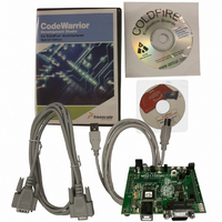
KIT DEMO FOR MCF5211
Manufacturer
Freescale Semiconductor
Series
ColdFire®r
Type
MPUr
Datasheet
1.M5211DEMO.pdf
(18 pages)
Specifications of M5211DEMO
Contents
SBC, Cables and Software
Processor To Be Evaluated
MCF521x
Data Bus Width
12 bit
Interface Type
RS-232, USB
Operating Supply Voltage
9 V
Silicon Manufacturer
Freescale
Core Architecture
Coldfire
Core Sub-architecture
Coldfire V2
Silicon Core Number
MCF52
Silicon Family Name
MCF521x
Rohs Compliant
Yes
For Use With/related Products
MCF5211, MCF5212, MCF5213
Lead Free Status / RoHS Status
Lead free / RoHS Compliant


Low-Power Modes
switch is released. An external pullup on the RSTI* line prevents spurious resets and allowing normal
operation.
8.2
The MCF5211 utilizes an internal Low-Voltage Detect (LVD) to protect against under-voltage conditions.
The LVD is enabled out of RESET. Consult the MCF5213 Integrated Microcontroller Reference Manual
for details on configuring LVD operation.
8.3
The RESET LED turns on when the MCU is in RESET and remains on for the duration of a valid RSTO*
signal.
9
The MCF5211 supports several operational modes designed to reduce power consumption. Low-power
modes include Wait, Doze, Stop, and Halt. Refer to the MCF5213 Microcontroller Family Hardware
Specification and the MCF5213 Integrated Microcontroller Reference Manual for details on configuring
and using the various low-power modes.
10
Timing for the M5211DEMO is provided by an on-chip, 8 MHz relaxation oscillator in default
configuration. Resistor R23 causes the MCU to select the internal oscillator as the timing source out of
reset. Refer to the M5213 Integrated Microcontroller Reference Manual for details on use and
configuration of internal timing.
Pad locations for an external crystal oscillator have been provided but not populated in default
configurations. The external oscillator is connected to the XTAL and EXTAL inputs. To implement an
external crystal oscillator simply remove R23, install the oscillator and related circuitry. The XTAL_EN
shunt must be installed to enable external timing operation.
Pad locations for an optional 32.768 kHz have also been provided but not populated. The 32.768 kHz
timing input is connected to GPT0 and GPT1 inputs. To implement this timing input, simply install the
timing source and related circuitry.
12
Low-Voltage Detect
Reset Indicator
Low-Power Modes
Timing
XTAL_EN
XTAL_EN
OFF
ON
Demonstration Board for Freescale MCF5211, Rev. 1
Enables external crystal oscillator input to MCU
Disables external crystal oscillator input to MCU
Figure 8. OSC_EN Option Header
Freescale Semiconductor
Related parts for M5211DEMO
Image
Part Number
Description
Manufacturer
Datasheet
Request
R

Part Number:
Description:
Manufacturer:
Freescale Semiconductor, Inc
Datasheet:
Part Number:
Description:
Manufacturer:
Freescale Semiconductor, Inc
Datasheet:
Part Number:
Description:
Manufacturer:
Freescale Semiconductor, Inc
Datasheet:
Part Number:
Description:
Manufacturer:
Freescale Semiconductor, Inc
Datasheet:
Part Number:
Description:
Manufacturer:
Freescale Semiconductor, Inc
Datasheet:
Part Number:
Description:
Manufacturer:
Freescale Semiconductor, Inc
Datasheet:
Part Number:
Description:
Manufacturer:
Freescale Semiconductor, Inc
Datasheet:
Part Number:
Description:
Manufacturer:
Freescale Semiconductor, Inc
Datasheet:
Part Number:
Description:
Manufacturer:
Freescale Semiconductor, Inc
Datasheet:
Part Number:
Description:
Manufacturer:
Freescale Semiconductor, Inc
Datasheet:
Part Number:
Description:
Manufacturer:
Freescale Semiconductor, Inc
Datasheet:
Part Number:
Description:
Manufacturer:
Freescale Semiconductor, Inc
Datasheet:
Part Number:
Description:
Manufacturer:
Freescale Semiconductor, Inc
Datasheet:
Part Number:
Description:
Manufacturer:
Freescale Semiconductor, Inc
Datasheet:
Part Number:
Description:
Manufacturer:
Freescale Semiconductor, Inc
Datasheet: