DM163014 Microchip Technology, DM163014 Datasheet - Page 16
DM163014
Manufacturer Part Number
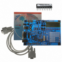
DM163014
Description
BOARD DEMO PICDEM4 12F629,16F630
Manufacturer
Microchip Technology
Type
MCUr
Specifications of DM163014
Contents
Board, Cable, CD
Processor To Be Evaluated
PIC18F1320 and PIC16F627A
Interface Type
RS-232
Silicon Manufacturer
Microchip
Silicon Core Number
PIC12F629, PIC12F675, PIC16F630, PIC16F676
Silicon Family Name
PIC12F, PIC16F And PIC18F
Kit Contents
PICDEM 4 PCB, MCU Samples, Cables, CD
Rohs Compliant
NA
Lead Free Status / RoHS Status
Lead free / RoHS Compliant
For Use With/related Products
PIC12F, PIC16F, PIC18F (8,14,18 pins)
Lead Free Status / Rohs Status
Lead free / RoHS Compliant
Other names
DM163014R
DM163014R
Q1543373
DM163014R
Q1543373
Available stocks
Company
Part Number
Manufacturer
Quantity
Price
Company:

Part Number:
DM163014
Manufacturer:
Microchip Technology
Quantity:
135


PICDEM 4 User’s Guide
A.5
A.6
A.7
A.8
DS51337A-page 12
SWITCHES
OSCILLATOR OPTIONS
ANALOG INPUT
ICD CONNECTOR
Three switches provide the following functions:
• S1 - Active low switch connected to RA4
• S2 - MCLR to hard reset the processor
• S3 - Active low switch connected to RB0
Switch S2 has a debounce capacitor, whereas S1 and S3 do not, allowing the user to
investigate debounce techniques.
When pressed, the switches are grounded; when idle, they are pulled high (+5V).
• RC oscillator (2 MHz approximately) supplied. This oscillator may be disabled by
• Pads provided for user furnished crystal/resonator and two capacitors (Y3).
• Socket provided for a canned oscillator (Y1).
• 32.768 kHz (watch type) crystal for Timer1 (Y2). This oscillator can be disabled by
There are four 5 kΩ potentiometers (R12, R15, R33, R34) on the PICDEM 4 board.
These are all connected to PORTA (RA0-RA3), and can be adjusted from V
to provide an analog input to the devices with an A/D or Comparator module.
Potentiometers R12, R15, R33, and R34 all have individual jumpers. For a potentiom-
eter to function, its specific jumper must be on. The jumper removed will allow for other
I/O functions to take place. For all of the potentiometers to be functional, these jumpers
must be configured as follows:
• J22 - OFF (PORTA LEDs)
• J24 - ON
• J25 - ON
• If J26 is ON, then J23 is OFF
• If J27 is ON, then J28 is OFF
The above conditions will enable all potentiometers.
By way of the modular connector (J5), the MPLAB ICD 2 can be connected for low cost
debugging. The ICD connector utilizes RB6 and RB7 of the microcontroller for in-circuit
debugging. For ICD operation, the Real-time Clock connections to the microcontroller
must be disabled. For ICD operation, these jumpers must be configured as follows:
• J7 - OFF (RTC)
• J9 - OFF (RTC)
• J21 - OFF (PORTB LEDs)
removing jumper J14.
removing jumpers J7 and J9.
2003 Microchip Technology Inc.
SS
to V
DD
Related parts for DM163014
Image
Part Number
Description
Manufacturer
Datasheet
Request
R

Part Number:
Description:
Manufacturer:
Microchip Technology Inc.
Datasheet:
Part Number:
Description:
Manufacturer:
Microchip Technology Inc.
Datasheet:
Part Number:
Description:
Manufacturer:
Microchip Technology Inc.
Datasheet:
Part Number:
Description:
Manufacturer:
Microchip Technology Inc.
Datasheet:
Part Number:
Description:
Manufacturer:
Microchip Technology Inc.
Datasheet:
Part Number:
Description:
Manufacturer:
Microchip Technology Inc.
Datasheet:
Part Number:
Description:
Manufacturer:
Microchip Technology Inc.
Datasheet:
Part Number:
Description:
Manufacturer:
Microchip Technology Inc.
Datasheet: