DM163014 Microchip Technology, DM163014 Datasheet - Page 11
DM163014
Manufacturer Part Number
DM163014
Description
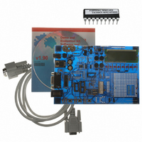
BOARD DEMO PICDEM4 12F629,16F630
Manufacturer
Microchip Technology
Type
MCUr
Specifications of DM163014
Contents
Board, Cable, CD
Processor To Be Evaluated
PIC18F1320 and PIC16F627A
Interface Type
RS-232
Silicon Manufacturer
Microchip
Silicon Core Number
PIC12F629, PIC12F675, PIC16F630, PIC16F676
Silicon Family Name
PIC12F, PIC16F And PIC18F
Kit Contents
PICDEM 4 PCB, MCU Samples, Cables, CD
Rohs Compliant
NA
Lead Free Status / RoHS Status
Lead free / RoHS Compliant
For Use With/related Products
PIC12F, PIC16F, PIC18F (8,14,18 pins)
Lead Free Status / Rohs Status
Lead free / RoHS Compliant
Other names
DM163014R
DM163014R
Q1543373
DM163014R
Q1543373
Available stocks
Company
Part Number
Manufacturer
Quantity
Price
Company:

Part Number:
DM163014
Manufacturer:
Microchip Technology
Quantity:
135


3.1
2003 Microchip Technology Inc.
TUTORIAL FIRMWARE OPERATION
The tutorial program is preprogrammed into the sample device (for example,
p16PDEM4_Demo.hex for a PIC16XXXX device and p18PDEM4_Demo.hex for a
PIC18XXXX device). Also, this program is on the included CD-ROM program disk for
user reference (i.e., if the sample device has been reprogrammed with another
program, the tutorial may be reprogrammed into the device).
For detailed information on the PICDEM 4 hardware, please refer to Appendix A.
The PIC18F tutorial firmware is made up of two components, which are individually
displayed on the LCD. The PIC
system clock source.
1. Voltmeter
2. Clock
The PIC16F tutorial firmware is made up of one component, which uses the comparator
module and potentiometers R12, R15, R33, and R34. Turning the potentiometers will
vary the voltages to the PIC16 inputs, thereby changing the results of the comparator
outputs. The LCD will be used for displaying these results.
This mode uses the A/D module to measure the voltage of the R33 pot and dis-
plays a voltage between 0.00V and 5.00V on the LCD. Voltage is continually
updated until the mode is exited by pressing SW3 (RB0).
Once this mode is entered from the main menu, a real-time clock will start count-
ing from 00:00:00. The Timer1 module and a 32 kHz clock crystal is used to
establish a Real-Time Clock. By pressing SW1, the clock time can be set to the
user's preference. After SW1 has been pressed, the cursor will flash over the
hours digits. Press SW1 and the cursor will now flash over the minutes digits.
SW3 is used to increment hours and minutes whenever the cursor is flashing
over either. After the minutes have been set, press SW1 and the time will be set
and the LCD is returned to an active clock display.
Chapter 3. Tutorial
PICDEM 4 User’s Guide
®
microcontroller’s internal RC oscillator is used as the
DS51337A-page 7
Related parts for DM163014
Image
Part Number
Description
Manufacturer
Datasheet
Request
R

Part Number:
Description:
Manufacturer:
Microchip Technology Inc.
Datasheet:
Part Number:
Description:
Manufacturer:
Microchip Technology Inc.
Datasheet:
Part Number:
Description:
Manufacturer:
Microchip Technology Inc.
Datasheet:
Part Number:
Description:
Manufacturer:
Microchip Technology Inc.
Datasheet:
Part Number:
Description:
Manufacturer:
Microchip Technology Inc.
Datasheet:
Part Number:
Description:
Manufacturer:
Microchip Technology Inc.
Datasheet:
Part Number:
Description:
Manufacturer:
Microchip Technology Inc.
Datasheet:
Part Number:
Description:
Manufacturer:
Microchip Technology Inc.
Datasheet: